Integrated brushless starter/generator system

a starter/generator and brushless technology, applied in the direction of mechanical energy handling, magnetic circuit rotating parts, magnetic circuit shape/form/construction, etc., can solve the problems of power and fuel robbery, limited electric generation in such units,

Active Publication Date: 2013-05-28
GENERAL ELECTRIC CO
View PDF43 Cites 29 Cited by
  • Summary
  • Abstract
  • Description
  • Claims
  • Application Information

AI Technical Summary

Benefits of technology

[0010]The brushless starter / generator may be incorporated in an aircraft gas turbine engine integrated brushless starter / generator system in which the brushless starter / generator is mounted to an engine accessory gearbox. The rotor extends into the gearbox and is operably connected to a power take-off shaft within the gearbox or to a gear train operably connected to the power take-off shaft within the gearbox. The rotor shaft may be rotatably supported by a shaft bearing in the accessory gearbox. The rotor shaft may be rotatably supported by a shaft bearing in a gearbox casing of the accessory gearbox.

Problems solved by technology

The electrical generation in such units is limited in amperage and often require complicated cooling apparatus including cooling fans and ducts which leads to power and fuel robbing parasitic flows required for air cooled starter / generators using brushes.

Method used


Image

  • Integrated brushless starter/generator system
  • Integrated brushless starter/generator system
  • Integrated brushless starter/generator system

Examples


Embodiment Construction

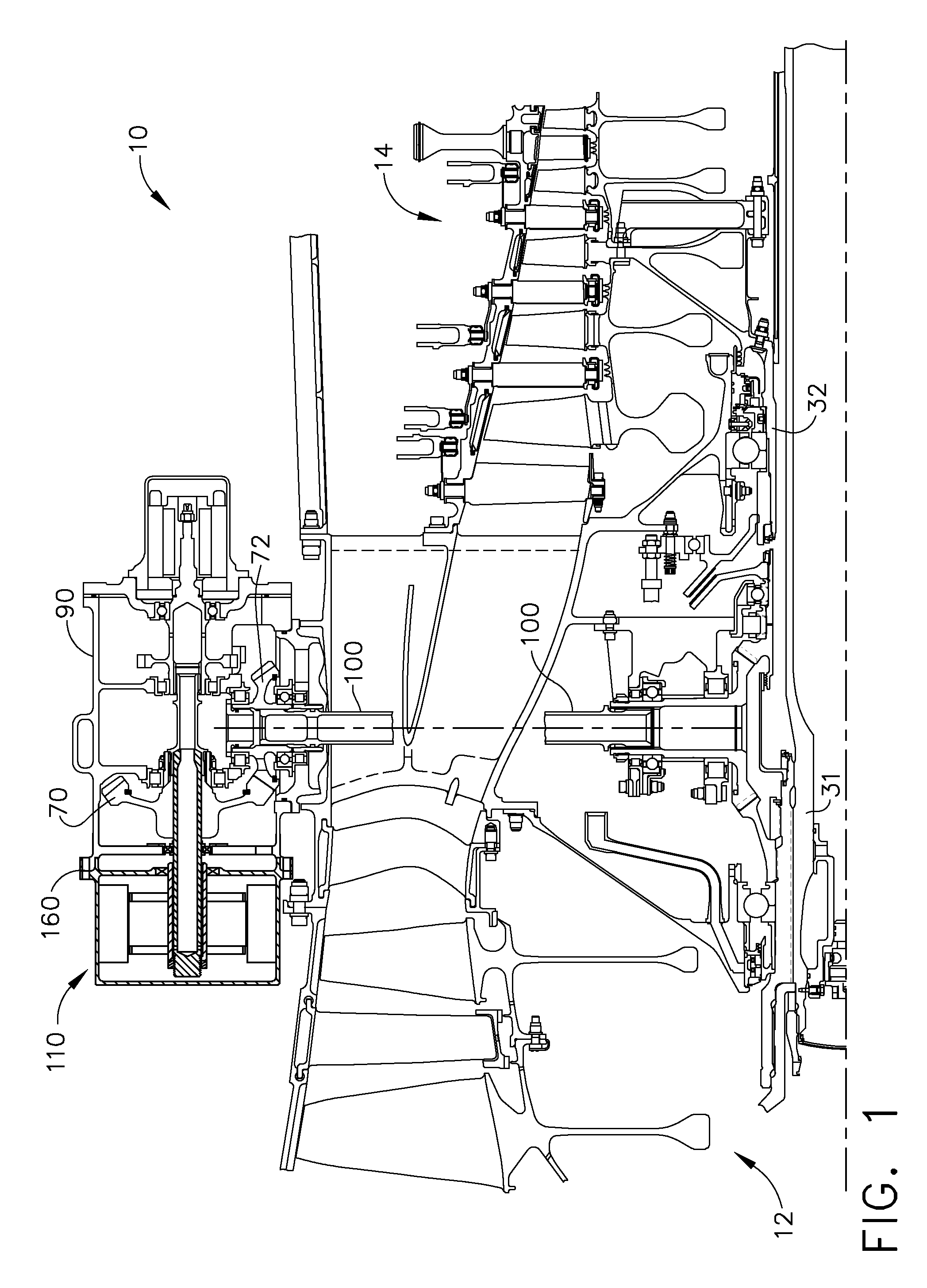
[0020]Illustrated in FIG. 1 is an exemplary embodiment of a gas turbine engine 10 having a longitudinal axis 11. The engine 10 includes a fan section 12 followed by a core engine as represented by a high pressure compressor 14. The high pressure compressor 14 is driven via a first shaft 32 by a high pressure turbine (not illustrated). The fan section12 is driven via a second shaft 31 by a low-pressure turbine (not illustrated) downstream of the core engine.

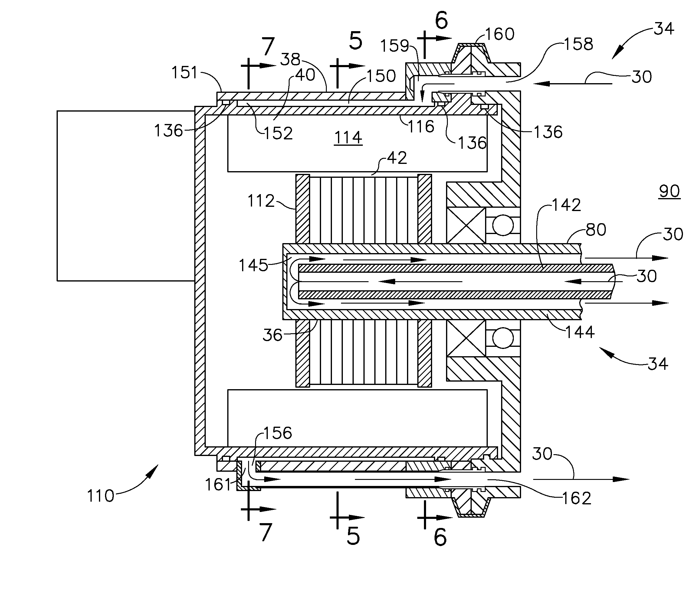
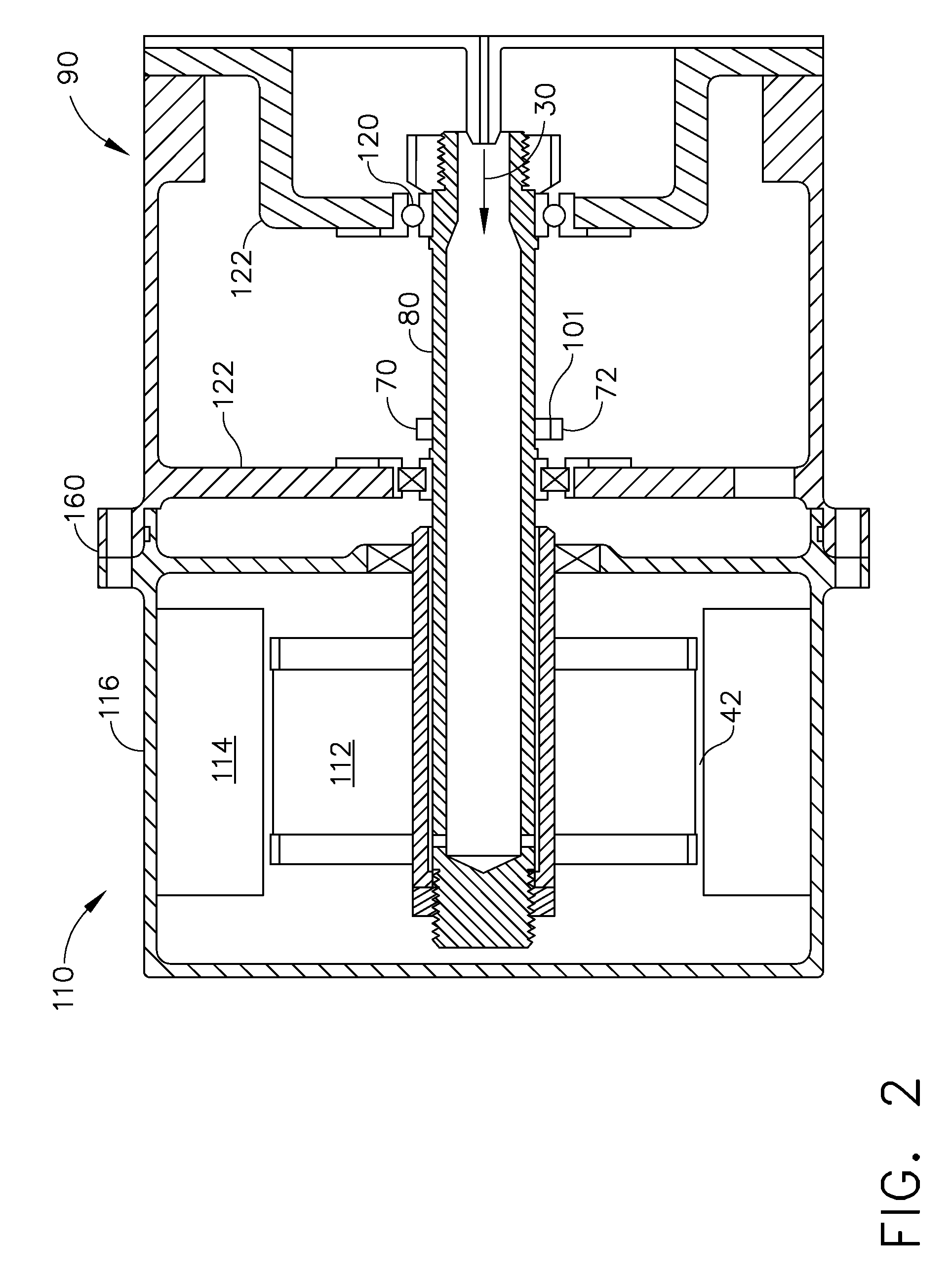
[0021]A brushless starter / generator 110 (BSG) is mounted to an engine accessory gearbox 90 and includes a rotor shaft 80 which is operably connected to an exemplary power take-off shaft 100 or alternatively to a gear train 101 (illustrated schematically in FIG. 2) operably connected to the power take-off shaft 100 within the engine accessory gearbox 90. A drive shaft bevel gear 70 fixedly mounted on the rotor shaft 80 engages a power take-off shaft bevel gear 72 mounted to the power take-off shaft 100. When the brushless starter / g...


PUM


Abstract

A brushless starter / generator includes a rotor rotatably mounted within a stator mounted within a housing and an oil cooling system using cooling oil from an engine accessory gearbox for cooling the rotor and the stator. The rotor is fixedly mounted on a rotor shaft having a rotor heat exchanger disposed therein. A stator heat exchanger for cooling the stator includes an oil jacket around the housing. The stator heat exchanger includes a grooved tube around the housing and axially extending axial passages connected to annular inlet and outlet manifolds in the grooved tube. The rotor shaft is operably connected to a power take-off shaft within the gearbox and rotatably supported by a shaft bearing in a gearbox casing of the accessory gearbox. The oil cooling system is a dry cavity oil cooling system which prevents cooling oil from entering an air gap between the rotor and the stator.

Description

BACKGROUND OF THE INVENTION[0001]1. Field of the Invention[0002]The present invention relates to aircraft gas turbine engine starters and generators.[0003]2. Description of Related Art[0004]Aircraft gas turbine engines typically include a fan section followed by a core engine having, in serial flow arrangement, a compressor which compresses airflow entering the engine, a combustor which burns a mixture of fuel and air, and a high-pressure turbine section followed by a low pressure turbine section which extracts energy from airflow discharged from the core engine to power the fan section which generates thrust.[0005]Aircraft and aircraft engine accessories are mechanically driven by the engine through a power take-off shaft connected to an engine accessory gearbox. Among the accessories mounted to the gearbox is a starter motor for starting the gas turbine engine and a generator to generate electrical power for the aircraft. It is known to provide a single starter / generator to provid...

Claims


Application Information

Patent Timeline
Patent Type & Authority Patents(United States)
IPC IPC(8): H02K9/00H02K9/20
CPCH02K1/20H02K1/32H02K5/20H02K9/19H02K5/203H02K9/197
Inventor SHAFER, DOUGLAS GEORGETOOT, PETER DAVID
Owner GENERAL ELECTRIC CO
Why Eureka
Try Eureka