
Exposure apparatus, exposure method, cleaning apparatus, and device manufacturing method

a technology of exposure apparatus and manufacturing method, which is applied in the direction of photomechanical treatment, printing, instruments, etc., can solve the problems of affecting the operation efficiency of the exposure process, the surface of the object which comes into contact with the liquid in the immersion space will become contaminated, and so as to reduce the deterioration of throughput in the exposure process, inhibit the effect of any reduction in productivity and inhibit the reduction of operating efficiency

Inactive Publication Date: 2013-05-28
NIKON CORP
View PDF35 Cites 0 Cited by
  • Summary
  • Abstract
  • Description
  • Claims
  • Application Information

AI Technical Summary

Benefits of technology

[0025]According to some aspects of the present invention, it is possible to reduce any deterioration in throughput in exposure process and to inhibit any reduction in productivity.
[0026]According to some aspects of the present invention, it is possible to perform a cleaning operation while inhibiting any reduction in operating efficiency.

Problems solved by technology

If the delivery operations of the shutter member require considerable time, there is a possibility of deterioration in throughput.
Furthermore, in a liquid immersion exposure apparatus, there is a possibility that a surface of an object which comes into contact with the liquid in the immersion space will become contaminated.
For example, if the surface of a component which has been placed in the vicinity of a substrate is left in a contaminated state, then the surface of the substrate becomes contaminated.
This results in the possibility of exposure defects occurring and defective devices being created.
On the other hand, cleaning operations require considerable time, and there is a possibility such that the operating efficiency of the exposure apparatus is reduced, and there is a deterioration in throughput.

Method used


Image

  • Exposure apparatus, exposure method, cleaning apparatus, and device manufacturing method
  • Exposure apparatus, exposure method, cleaning apparatus, and device manufacturing method
  • Exposure apparatus, exposure method, cleaning apparatus, and device manufacturing method

Examples


Embodiment Construction

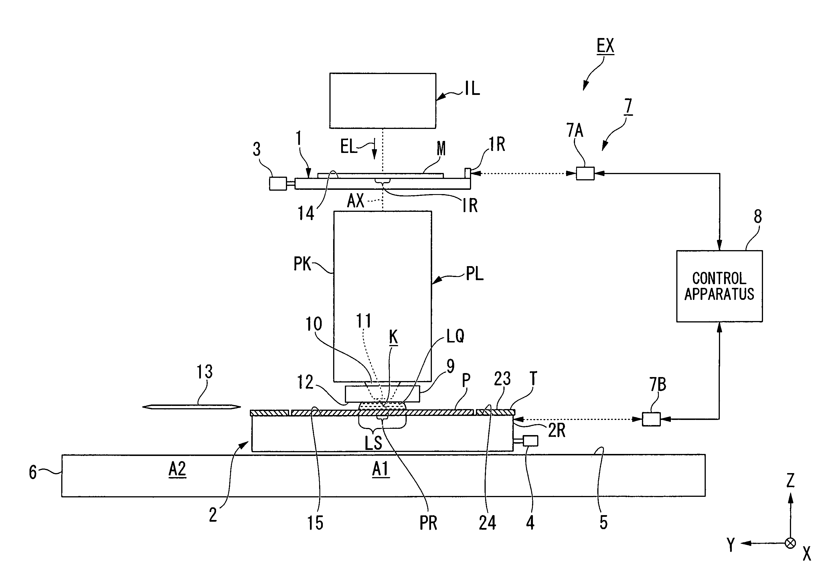
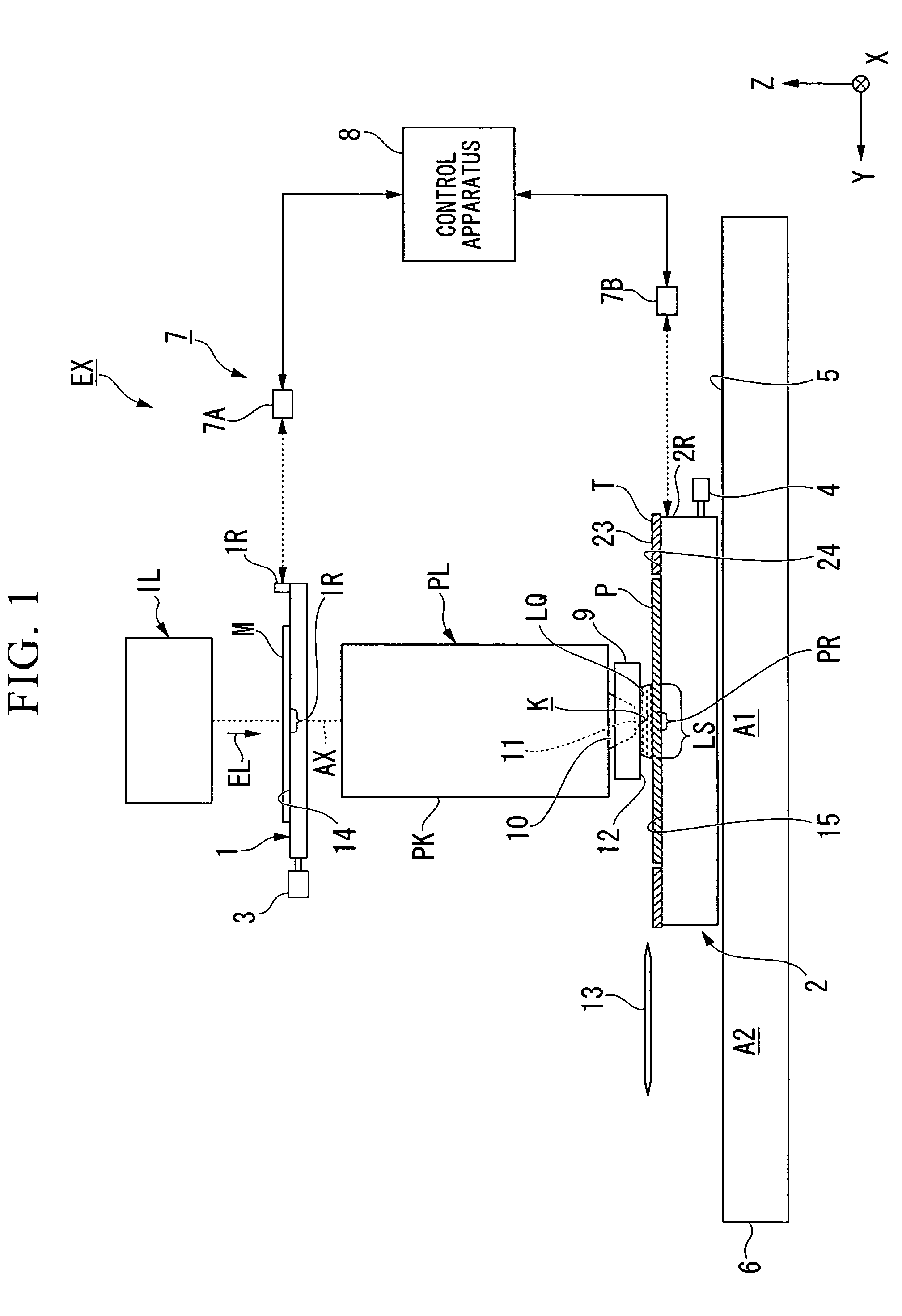
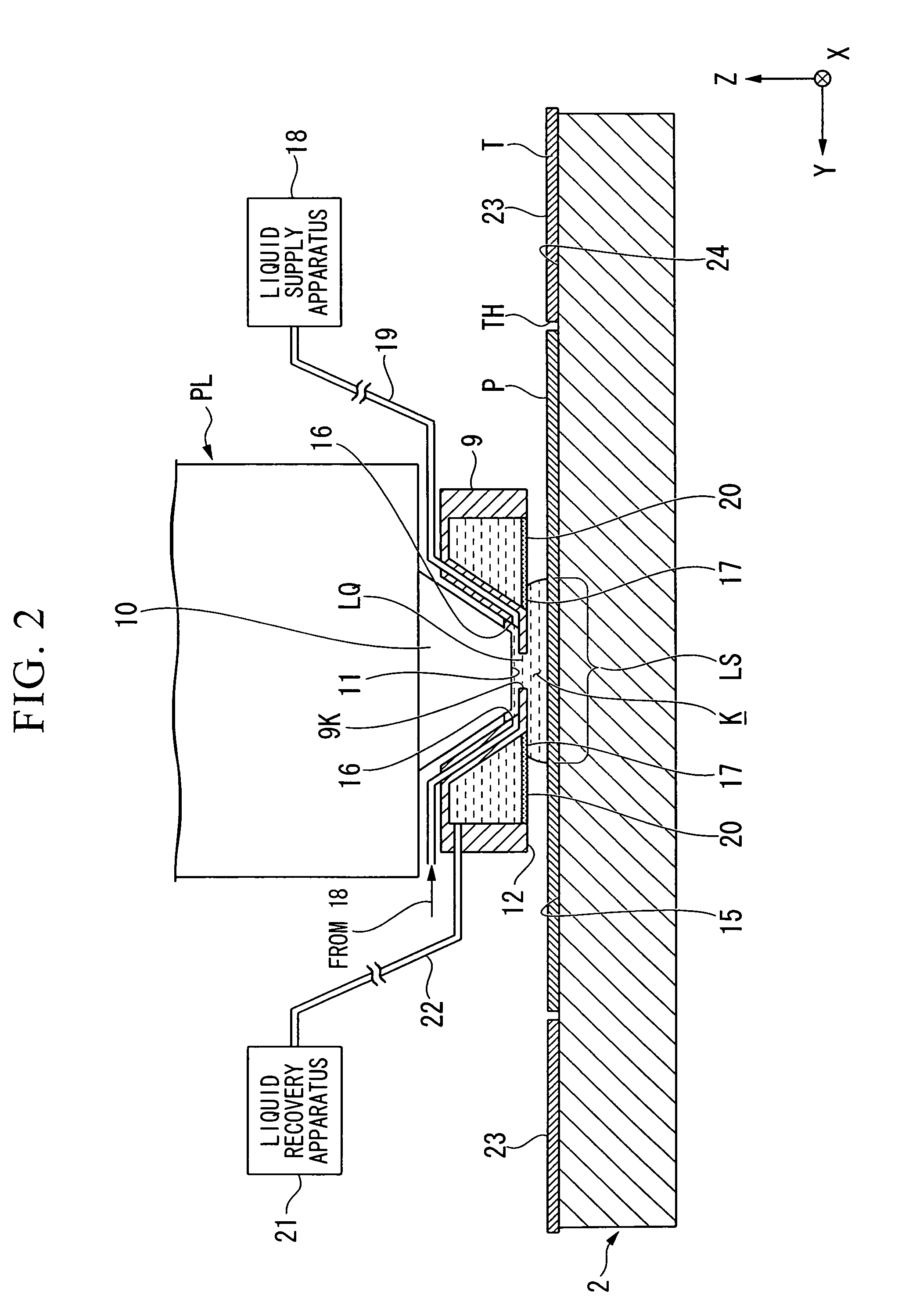
[0047]Embodiments of the present invention will now be described with reference made to the drawings, however, the present invention is not limited to these. In the description below, an XYZ rectangular coordinate system is set, and positional relationships between the respective components are described with reference made to this XYZ rectangular coordinate system. A predetermined direction within a horizontal plane is taken as an X axial direction, a direction which is orthogonal to the X axial direction within the horizontal plane is taken as a Y axial direction, while a direction which is orthogonal to both the X axial direction and the Y axial direction (namely, a vertical direction) is taken as a Z axial direction. Moreover, rotation (i.e., tilt) directions around the X axis, the Y axis, and the Z axis are taken respectively as θX, θY, and θZ directions.

[0048]FIG. 1 is a schematic structural view showing an example of an exposure apparatus EX according to the present embodimen...


PUM


Abstract

An exposure apparatus exposes a substrate with exposure light via a liquid. The exposure apparatus includes: an optical member which has an emission surface from which the exposure light is emitted; a movable object which is able to move in a predetermined surface including a position facing the emission surface; and a predetermined component which is able to move between, the optical member and the movable object and which is able to form a space between which and the optical member a liquid is held.

Description

CROSS-REFERENCE TO RELATED APPLICATION[0001]This application is a non-provisional application claiming priority to and the benefit of U.S. provisional application No. 61 / 006,734, filed Jan. 29, 2008 and U.S. provisional application No. 61 / 006,765, filed Jan. 30, 2008, and claims priority to Japanese Patent Application No. 2007-340877, filed Dec. 28, 2007 and Japanese Patent Application No. 2007-340876, filed Dec. 28, 2007. The entire contents of which are incorporated herein by reference.BACKGROUND[0002]1. Field of the Invention[0003]The present invention relates to an exposure apparatus, an exposure method, a cleaning apparatus, and a device manufacturing method.[0004]2. Related Art[0005]In an exposure apparatus which is used in a photolithographic process, a liquid immersion exposure apparatus which exposes a substrate using exposure light via a liquid such as that described in Patent document 1 is known. In a liquid immersion exposure apparatus, at least a portion of an optical p...

Claims


Application Information

Patent Timeline
Patent Type & Authority Patents(United States)
IPC IPC(8): G03B27/42G03B27/52
CPCG03F7/70925G03F7/70341G03F7/2041G03F7/70933
Inventor SHIBAZAKI, YUICHI
Owner NIKON CORP
Learn More