
Touch pad module assembly structure

a technology of touch pad module and assembly structure, which is applied in the direction of instruments, static indicating devices, electrical apparatus casings/cabinets/drawers, etc., can solve the problem of difficulty in a thinner touch pad module, and achieve the effect of improving the assembly structure of the touch pad modul

Inactive Publication Date: 2013-06-04
QUANTA COMPUTER INC
View PDF7 Cites 8 Cited by
  • Summary
  • Abstract
  • Description
  • Claims
  • Application Information

AI Technical Summary

Benefits of technology

[0006]It is therefore an objective of the present invention to provide an improved touch pad module assembly structure.

Problems solved by technology

However, it is difficult for a thinner touch pad module to permit a user to sense a clear click feeling.

Method used


Image

  • Touch pad module assembly structure
  • Touch pad module assembly structure
  • Touch pad module assembly structure

Examples


Embodiment Construction

[0022]Reference will now be made in detail to the present preferred embodiments of the invention, examples of which are illustrated in the accompanying drawings. Wherever possible, the same reference numbers are used in the drawings and the description to refer to the same or like parts.

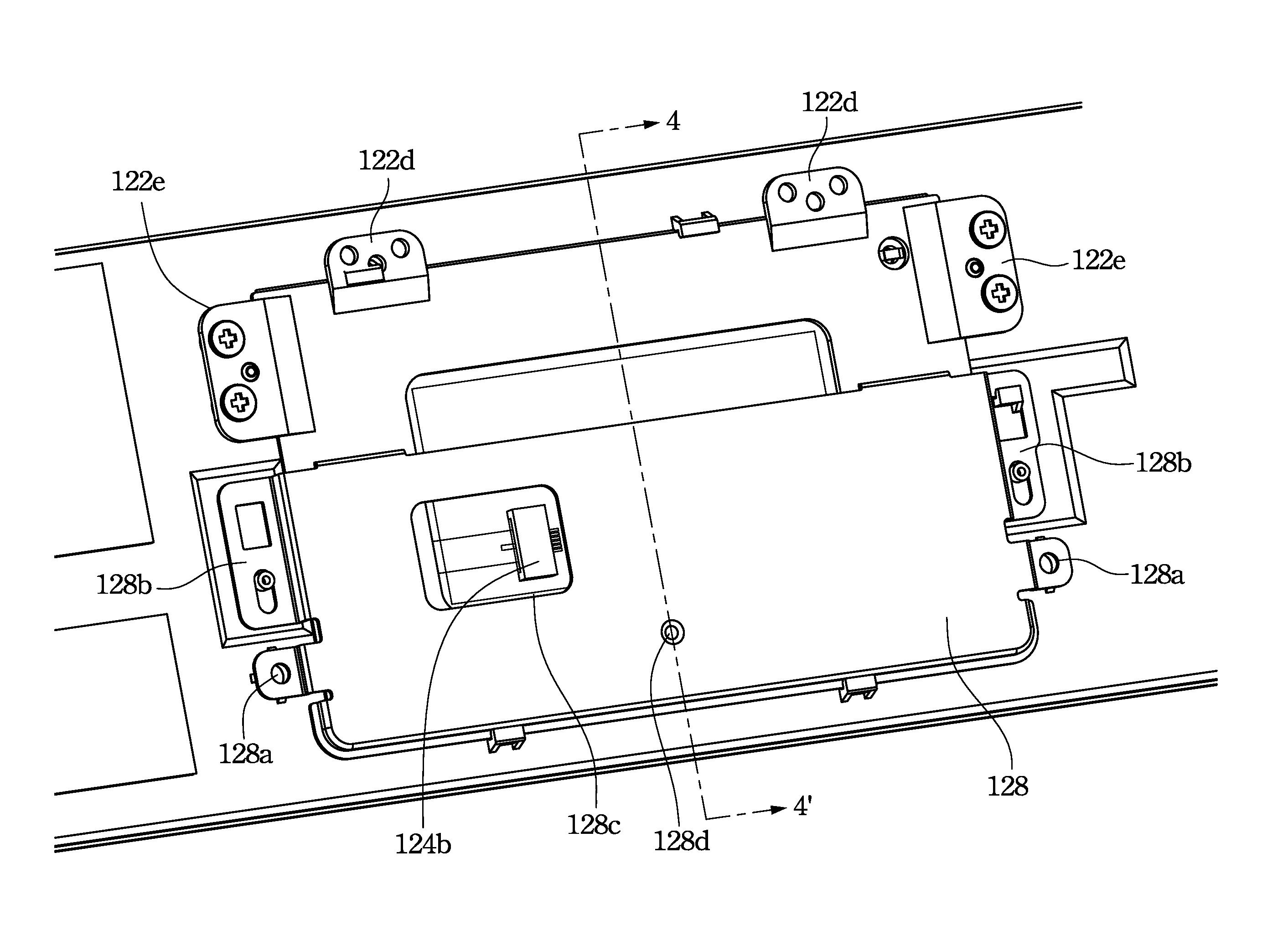
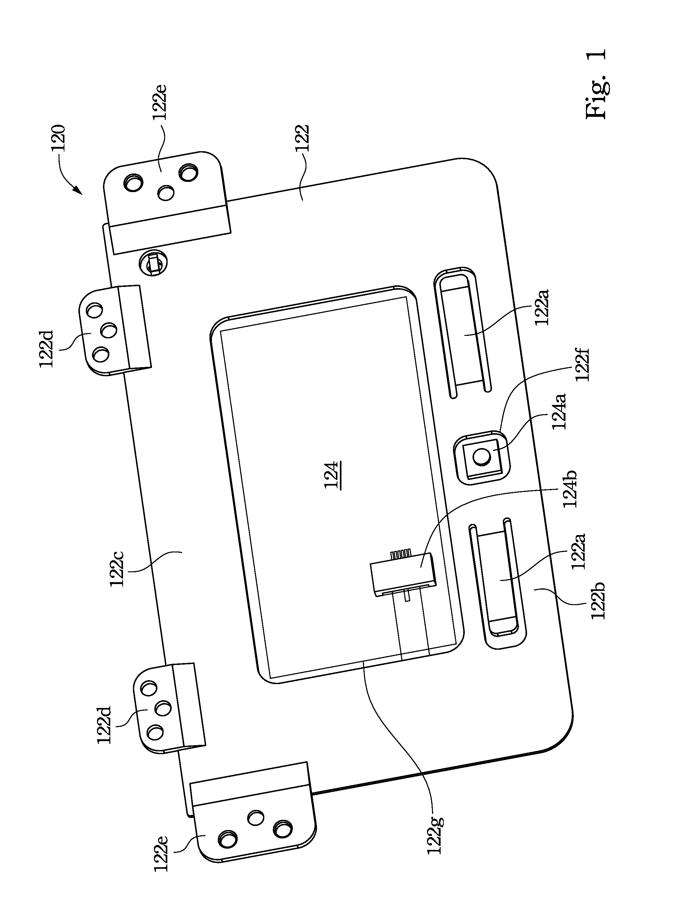
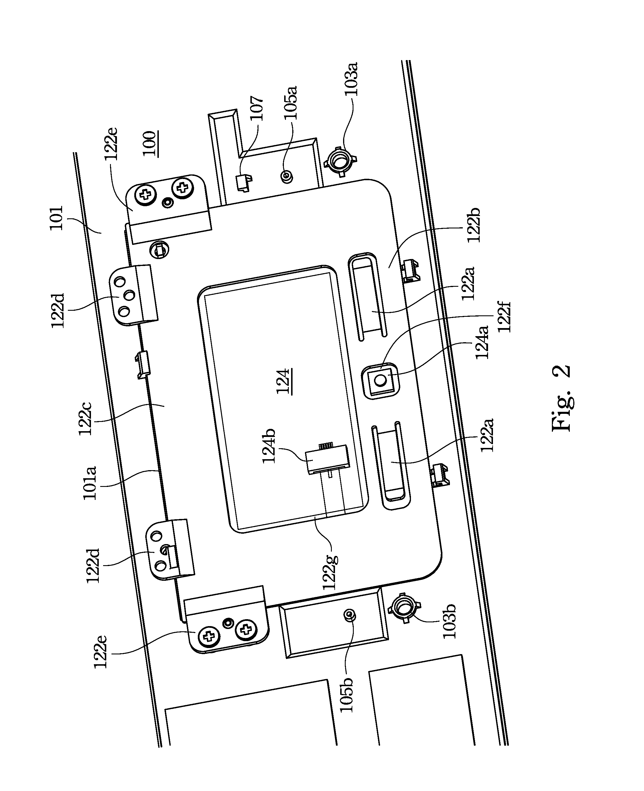
[0023]FIG. 1 illustrates a touch pad module according to one embodiment of this invention. In this embodiment, a touch pad module 120 includes a support member 122 and a circuit board 124. The circuit board 124 is attached over the plastic support member 122. An edge 122b of the support member 122 has a through hole 122f and a pair of resilient members 122a. Each resilient members 122a has an end secured to the support member 122 and an opposite free end sticking out of the support member 122. An opposite edge 122c of the support member 122 has connection members 122d and connection members 122e to be secured to a computer housing by a screw or bolt. Although both connection members 122d and connecti...


PUM


Abstract

A touch pad module assembly structure includes a housing, a touch pad module and a metal bracket. The housing includes a generally rectangular opening. The touch pad module is assembled into the opening. The touch pad module includes a support member and a circuit board. An edge of the support member has a through hole and a pair of resilient members. An opposite edge of the support member has a connection member secured to a surrounding surface of the opening. The circuit board is disposed over the support member and includes a switch aligned with the through hole. The metal bracket is secured to a surrounding edge of the opening to be in to contact with the switch and expose the connection member.

Description

RELATED APPLICATIONS[0001]This application claims priority to Taiwan Application Ser. No. 98218317, filed Oct. 5, 2009, which is herein incorporated by reference.BACKGROUND[0002]1. Field of Invention[0003]The present invention relates to a touch pad module. More particularly, the to present invention relates to a touch pad module of a computer device.[0004]2. Description of Related Art[0005]A touch pad module is one of the essential parts of each notebook computer in order to perform a computer mouse's function within an operation system. Because a thinner notebook computer is the mainstream in the market, a thinner touch pad module is needed to meet with this demand. However, it is difficult for a thinner touch pad module to permit a user to sense a clear click feeling. For the forgoing reasons, there is a need for improving the touch pad module assembly structure.SUMMARY[0006]It is therefore an objective of the present invention to provide an improved touch pad module assembly str...

Claims


Application Information

Patent Timeline
Patent Type & Authority Patents(United States)
IPC IPC(8): G09G5/00
CPCG06F3/03547
Inventor CHIANG, TSUNG-JULIN, HSIU-PEN
Owner QUANTA COMPUTER INC
Learn More