Power module assembly and assembling method thereof

a power module and power technology, applied in the field of power modules, can solve the problems of power device malfunction, power device heat generation, power device damage, etc., and achieve the effects of enhancing the power density of the power module assembly, optimizing the assembling structure of the power device, and enhancing the heat dissipation capacity of the power devi

Active Publication Date: 2019-02-28
DELTA ELECTRONICS SHANGHAI CO LTD
View PDF14 Cites 8 Cited by
  • Summary
  • Abstract
  • Description
  • Claims
  • Application Information

AI Technical Summary

Benefits of technology

[0006]An object of the present disclosure is to provide a power module assembly and an assembling method thereof. By employing the resilient set disposed between the circuit board and the housing to clamp the power devices, the assembling structure of the power devices is optimized, and the power devices are fastened easily and firmly, and the heat-dissipating capacity of the power devices is enhanced simultaneously, and the entire power density of the power module assembly is enhanced.

Problems solved by technology

When the power converting device is in operation, the plurality of power devices can produce a large amount of heat.
If the power devices are mounted on the heat-dissipating housing by locking the screws which directly pass through the screw holes of the power devices into the heat-dissipating housing, it will use up manpower of large quantity and damage the power devices easily to result in serious malfunction of the on-board power supply.
In addition, when the power devices are directly clamped to the heat-dissipating housing by the resilient steel sheet, the power density of the on-board power supply cannot be effectively raised.

Method used


Image

  • Power module assembly and assembling method thereof
  • Power module assembly and assembling method thereof
  • Power module assembly and assembling method thereof

Examples


Embodiment Construction

[0058]The present disclosure will now be described more specifically with reference to the following embodiments. It is to be noted that the following descriptions of preferred embodiments of this disclosure are presented herein for purpose of illustration and description only. It is not intended to be exhaustive or to be limited to the precise form disclosed.

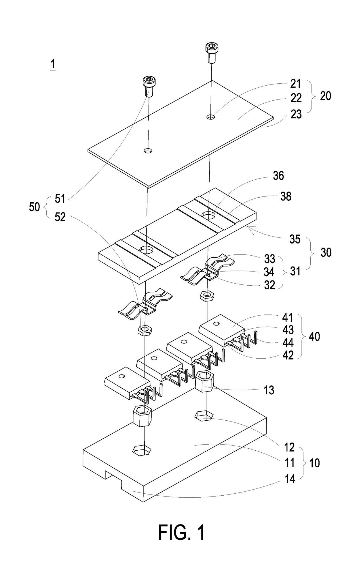
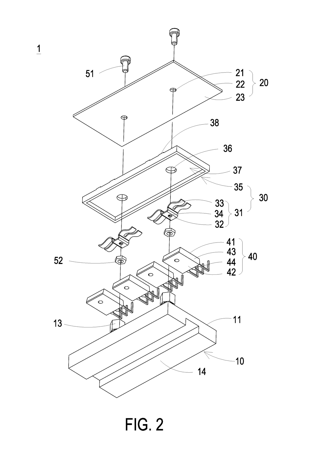
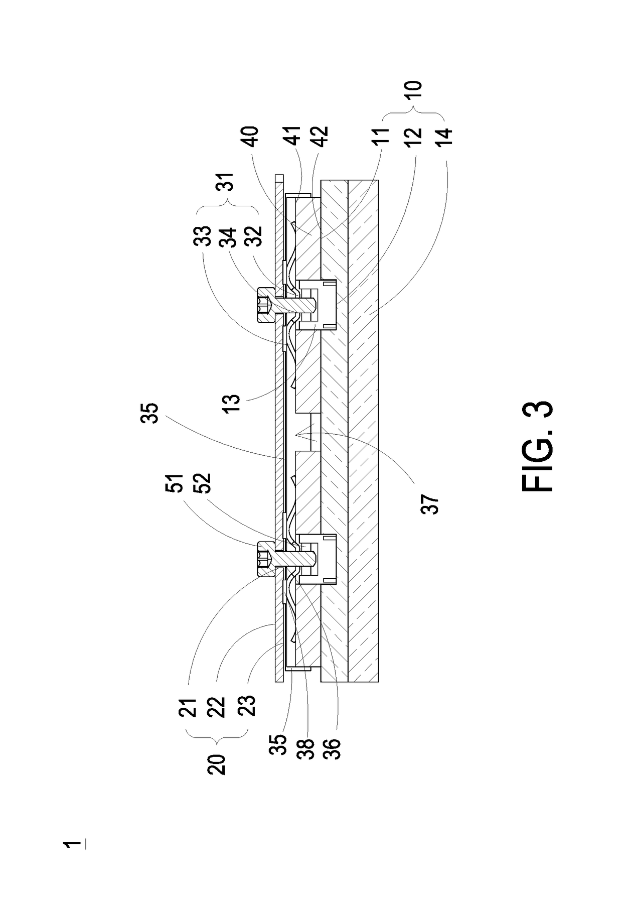
[0059]FIGS. 1 and 2 are an exploded view illustrating the power module assembly from different perspective points according to the first embodiment of the present disclosure. FIG. 3 is a cross sectional view illustrating the power module assembly according to the first embodiment of the present disclosure. Firstly, as shown in FIGS. 1, 2 and 3, the power module assembly 1 includes a housing 10, a circuit board 20, at least one resilient set 30, at least two power devices 40 and at least one fastening unit 50. The housing 10 includes at least one heat-dissipation surface 11. The circuit board 20 is configured to mount on the hou...


PUM


Abstract

The present disclosure provides a power module assembly and an assembling method thereof. The power module assembly includes a housing, a circuit board, at least one resilient set, at least two power devices, and at least one fastening unit. The housing includes at least one heat-dissipation surface. The at least one resilient set is disposed between the housing and the circuit board and includes at least one resilient piece. Each resilient piece includes a base section and two pushing fingers, so as to form an M-word shape or a bird-wings shape. The fastening unit is disposed between the two power devices, connected to the base section of the resilient piece and configured to drive the base section of the resilient piece, so that the two pushing fingers of the resilient piece push against the two power devices respectively and the two power devices are attached to the heat-dissipation surface.

Description

CROSS-REFERENCE TO RELATED APPLICATION[0001]This application claims priority to China Patent Application No. 201710729631.0, filed on Aug. 23, 2017, the entire contents of which are incorporated herein by reference for all purposes.FIELD OF THE DISCLOSURE[0002]The present disclosure relates to a power module, and more particularly to a power module assembly and an assembling method thereof.BACKGROUND OF THE DISCLOSURE[0003]An on-board power supply, also known as the power inverter, is a power converting device applied to the vehicle. The power converting device uses plurality of power devices to convert the external power into AC power or DC power. When the power converting device is in operation, the plurality of power devices can produce a large amount of heat. For avoiding the accumulated heat to influence the performance of the power converting device, it is desired to provide an effective thermal design for dissipating the heat generated from the power devices. Generally, the p...

Claims


Application Information

Patent Timeline
Patent Type & Authority Applications(United States)
IPC IPC(8): H05K7/20H02M7/00H05K1/18H05K1/02H05K3/30
CPCH05K7/209H02M7/003H05K7/20436H05K1/184H05K7/20927H05K1/0203H05K3/306H05K2201/10166H05K2201/10409H05K2201/10393H05K2201/10522H05K2201/10757H05K2201/10628H05K7/20845H05K7/2089H05K7/2049
Inventor GUO, WEIYOU, PEIAISUN, HAO
Owner DELTA ELECTRONICS SHANGHAI CO LTD
Why Eureka
Try Eureka