Light source unit, optical scanner including same, and image forming apparatus including the optical scanner
a technology of light source unit and scanner, which is applied in the direction of digital output to print units, lighting and heating apparatus, instruments, etc., can solve the problems of color drift, undesired shift of optical axes, and degradation of dot reproduction
- Summary
- Abstract
- Description
- Claims
- Application Information
AI Technical Summary
Problems solved by technology
Method used
Image
Examples
embodiment 2
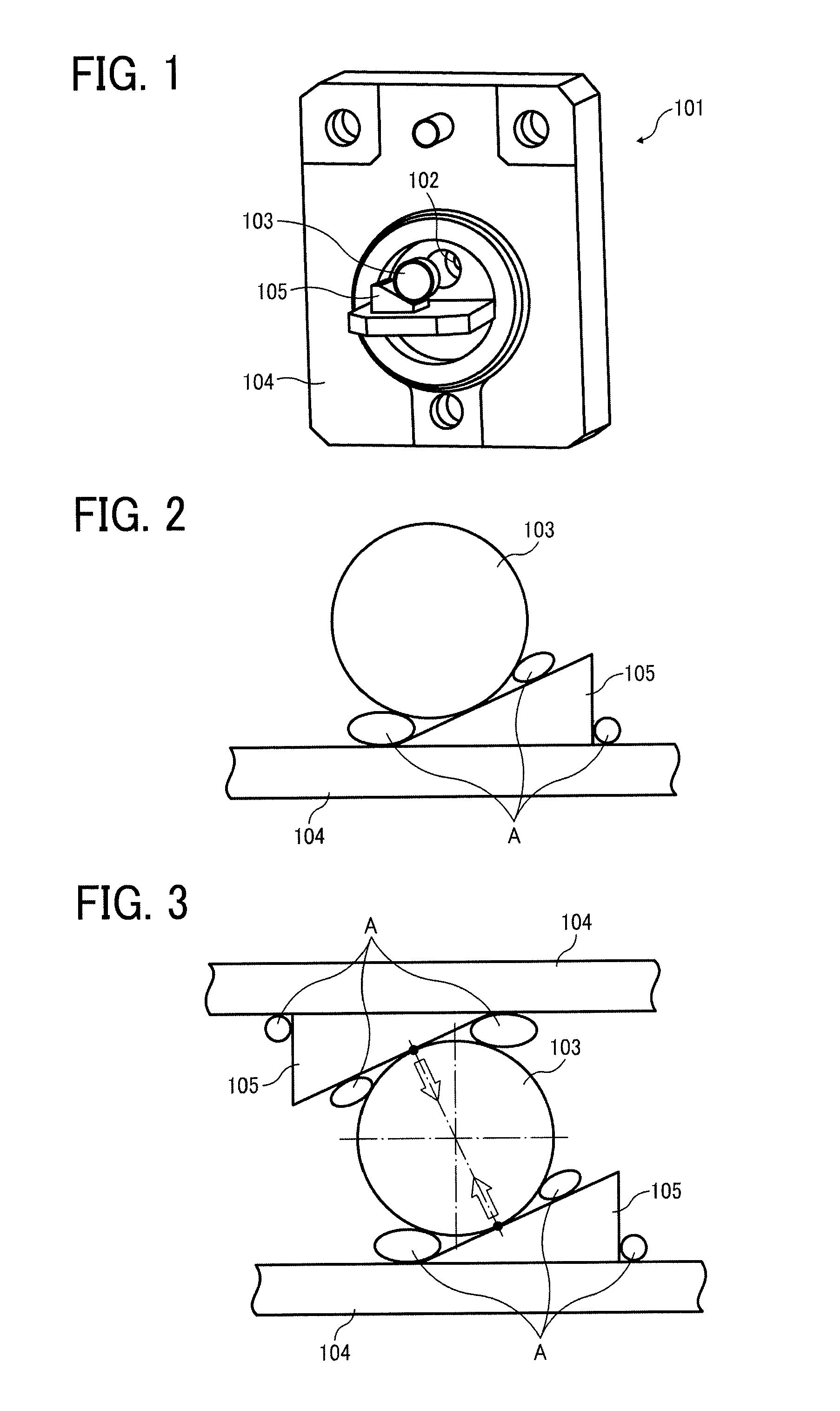
[0059]Referring now to FIG. 3, there is provided a schematic diagram illustrating a second illustrative embodiment of the positioning structure of the present invention. In the present embodiment, a plurality of support members 105, for example, two support members 105 are used, and the holder 104 includes two support member attachment surfaces, each provided at the top and the bottom of the holder 104.
[0060]The support members 105 are provided such that after adjusting the coupling lens 103, each of the support members 105 contacts the coupling lens 103 and the holder 104 to fix the position of the coupling lens 103.
[0061]As illustrated in FIG. 3, the position of the support members 105 is adjusted such that a line indicated by arrows in FIG. 3 that connects contact points of the coupling lens 103 and the support members 105 passes through a substantially center of the coupling lens 103. With this configuration, even if some force is applied to the coupling lens 103 due to a slight...
embodiment 3
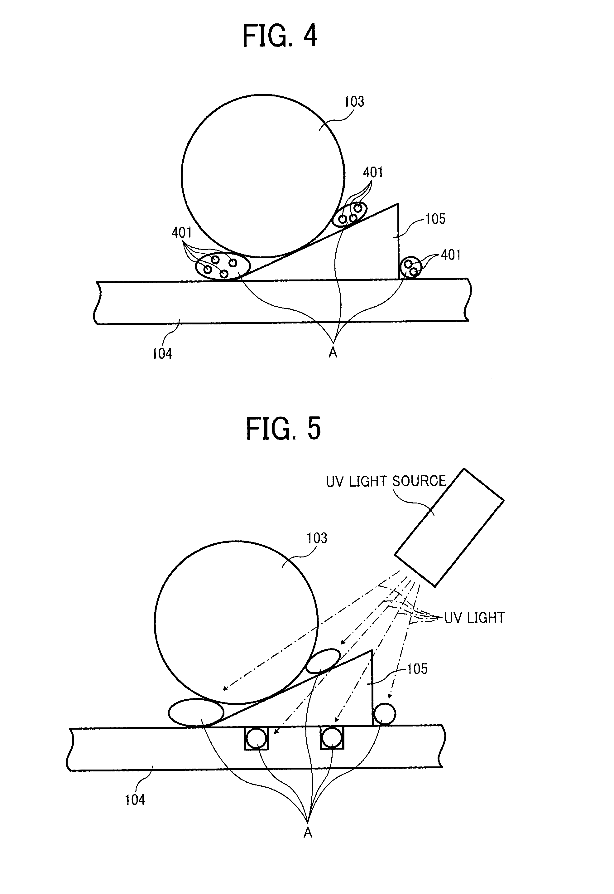
[0062]Referring now to FIG. 4, there is provided a schematic diagram illustrating a third illustrative embodiment of the positioning structure of the present invention. In the present embodiment, the adhesive agent A includes an additive 401 which is made from material different from the adhesive agent A. Materials suitable for the additive 401 include, but are not limited to, glass and acrylic resin.
[0063]Environmental changes including, but not limited to fluctuations of temperature in the light source unit 101, can cause the adhesive agent A to deform. In particular, the adhesive agent A expands and contracts. According to the present embodiment, the actual volume of the adhesive agent A is reduced by adding the additive 401 to the adhesive agent A so that an external force against the coupling lens 103, generated by the fluctuation of the volume of the adhesive agent A, is reduced.
[0064]Furthermore, an advantage of this configuration is that reducing the actual volume of the adh...
embodiment 4
[0073]Referring now to FIG. 5, there is provided a schematic diagram illustrating a fourth illustrative embodiment of the positioning structure of the present invention. According to the present embodiment, the support member 105 is formed of substantially transparent material. The material has a relatively high transmittance relative to an electromagnetic wave having a wavelength equal to or less than 1 μm. For example, the transmittance relative to the electromagnetic wave having the wavelength equal to or less than 1 μm is equal to or greater than 10%.
[0074]This configuration allows use of a photocurable resin as the adhesive agent A, thereby providing greater flexibility in choosing the application area of the adhesive agent A that fixes the support member 105. Consequently, the adhesive agent A can firmly fix the coupling lens 103, and thus deterioration of the characteristics of the light beam can be prevented. In other words, the characteristics of the light beam, similar to,...
PUM
 Abstract
Description
Claims
Application Information
 - R&D
- Intellectual Property
- Life Sciences
- Materials
- Tech Scout
- Unparalleled Data Quality
- Higher Quality Content
- 60% Fewer Hallucinations
Browse by: Latest US Patents, China's latest patents, Technical Efficacy Thesaurus, Application Domain, Technology Topic, Popular Technical Reports.
© 2025 PatSnap. All rights reserved.Legal|Privacy policy|Modern Slavery Act Transparency Statement|Sitemap|About US| Contact US: help@patsnap.com


