Linear actuator

a linear actuator and actuator technology, applied in the direction of toothed gearings, belts/chains/gearings, toothed gearings, etc., can solve the problems of increasing production costs, reducing the reliability of actuators, and actuators that require various limit switch units, so as to accurately control the stop position of actuators and reduce production costs. , the effect of simple device structure and simple assembly

Active Publication Date: 2013-06-11
MITSUBA CORP
View PDF22 Cites 14 Cited by
  • Summary
  • Abstract
  • Description
  • Claims
  • Application Information

AI Technical Summary

Benefits of technology

[0011]The object of the present invention is to provide a linear actuator that reduces the rise in costs and is excellent in terms of assembling, reliability and layout as well as being able to support an actuator having a different set of specifications in a flexible manner.
[0018]According to the linear actuator of the present invention, it is possible to accurately control the stop positions of the actuator even though the structure is simple. Since the structure of the device is simple, it is possible to make assembling work simple, and the causes of failure decrease. The reliability of the device also improves. If the striker is set according to the strokes of the actuator, it is easy to modify the specifications. Thus, it is not necessary to design and produce new components for each set of specifications, and it is possible to reduce production costs.

Problems solved by technology

However, such a linear actuator requires various limit switch units because of differences in the specifications (length of strokes) of actuators.
As a result, the problem is that the number of types of components increases, resulting in increases in production costs.
The deformation of the base plate could be a factor in decreasing the reliability of the actuator.
Furthermore, it is difficult to carry out soldering work on the long and thin base plate.
It is also difficult to make the long and thin base plate with a die, which is a factor in increasing costs.
Therefore, another problem is that the device becomes large in size and is not excellent in terms of layout.
The workability is not good and the structure of the device becomes complex.

Method used


Image

  • Linear actuator
  • Linear actuator
  • Linear actuator

Examples


Embodiment Construction

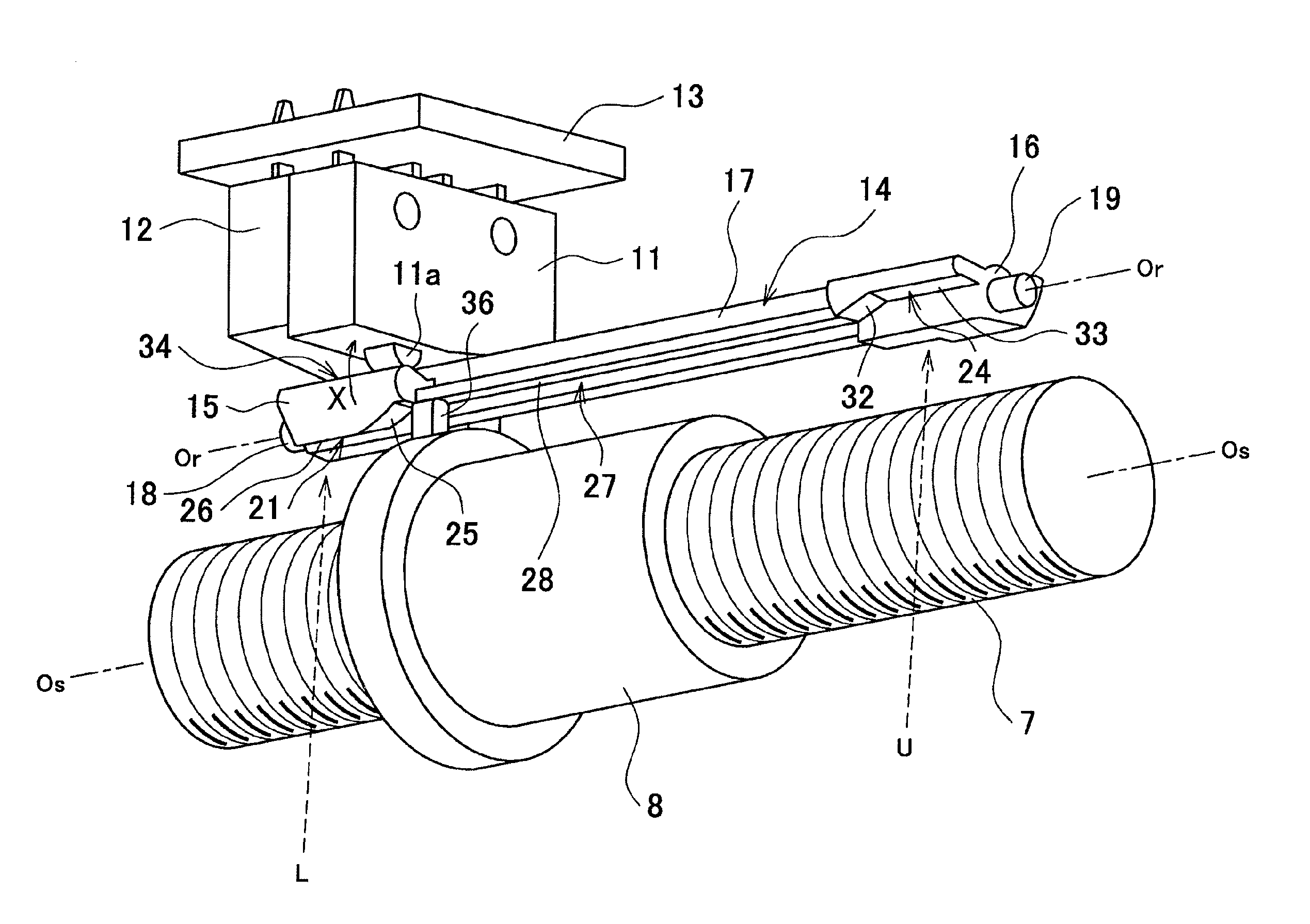
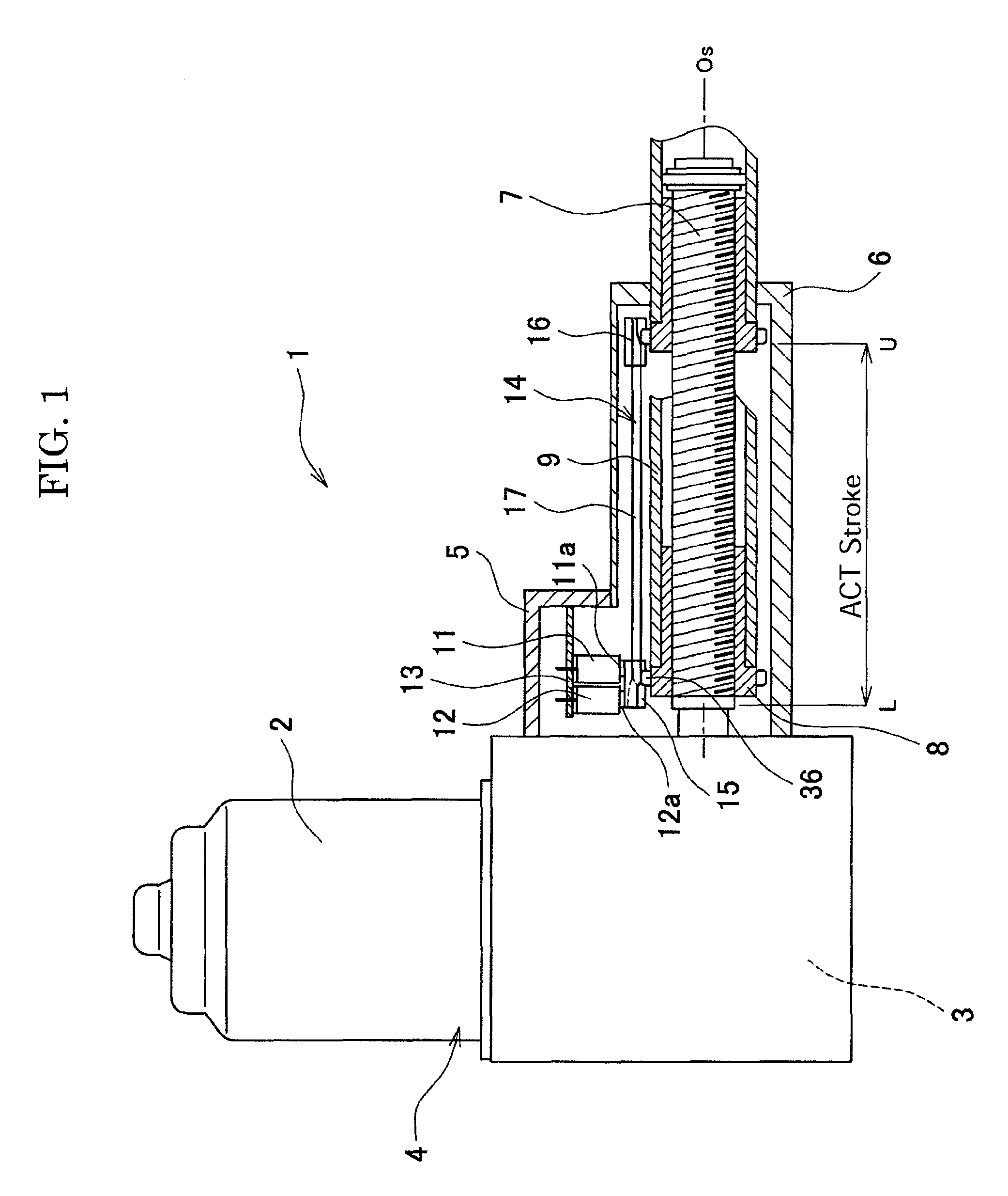
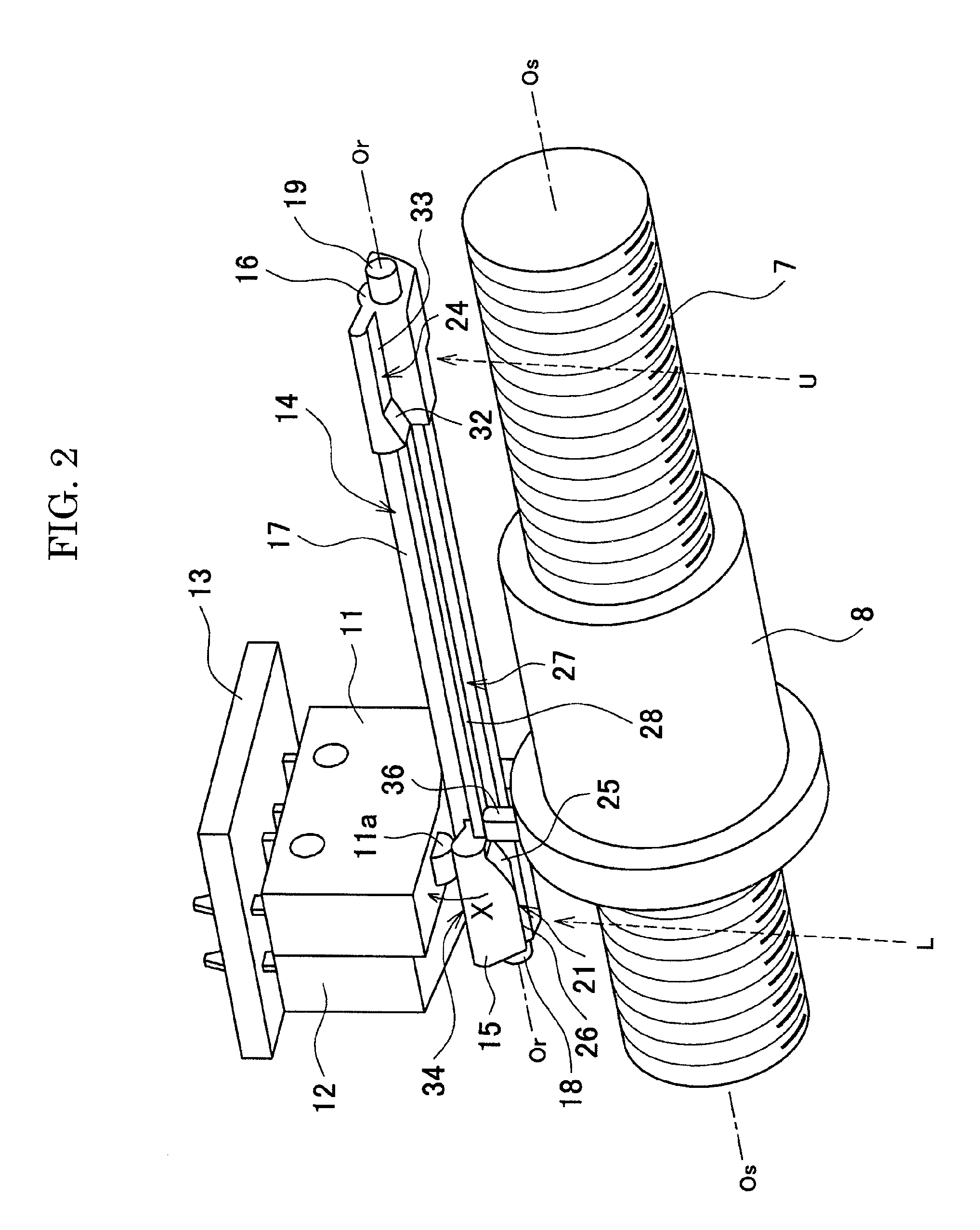
[0024]The following describes in detail an example of the present invention with reference to the accompanying drawings. FIG. 1 is an explanatory diagram showing the configuration of a linear actuator 1 according to an example of the present invention. The linear actuator 1 of the present example is for example used as a drive source to make a back-portion mat of a medical / nursing-care bed go up and down. The linear actuator 1 is equipped with a drive-source motor 2 and a motor unit 4 that houses a speed reduction mechanism unit 3. A main unit frame 5 is attached to the motor unit 4. A case 6 is attached to the frame 5. The case 6 houses a screw shaft 7, which is connected to the speed reduction mechanism unit 3, and a screw nut 8, which is threaded onto the shaft 7.

[0025]A piston (mobile object) 9 is attached to the screw nut 8. The piston 9 is designed to freely move in the axial direction (or the horizontal direction in FIG. 1) relative to the case 6. As the shaft 7 is driven and...


PUM


Abstract

The swinging operation of a rotary striker turns micro switches and, which detect the position of a piston, ON / OFF. The striker includes a lower-limit switch cam and an upper-limit switch cam. The cams and engage with switch bosses and that move together with the piston. When the piston is positioned at a lower-limit stop position L, the cam becomes engaged with the boss to make the striker swing in the X-direction and pushes a switch button of the switch. When the piston is positioned at an upper-limit stop position U, the cam becomes engaged with the boss to make the striker swing in the Y-direction and pushes a switch button of the switch.

Description

BACKGROUND OF THE INVENTION[0001]1. Field of the Invention[0002]The present invention relates to, for example, an electric-powered linear actuator used in an operating unit of a medical / nursing-care bed, and particularly to the functioning structure of a micro switch for limiting the operating range of the actuator.[0003]2. Related Art Statement[0004]In the medical and nursing-care sectors, an electric-powered bed which moves a bed upward or downward, reclines, and carries out other operations by electric-powered actuators has been widely used to reduce burden on patients and caretakers. For the electric-powered bed actuators, a linear actuator of a feed-screw type is used in many cases. The feed-screw type linear actuator is equipped with a shaft having a male screw section and a female screw member (feed nut) that is threaded onto the shaft. As the shaft is rotated by an electric motor, the female screw member moves along the shaft.[0005]The feed-screw type linear actuator is equi...

Claims


Application Information

Patent Timeline
Patent Type & Authority Patents(United States)
IPC IPC(8): F16H21/06
CPCF16H25/2015Y10T74/18688Y10T74/18056Y10T74/2101
Inventor INOUE, MASAKINAKAMURA, MASATOSUZUKI, MASATOSHIKUMAMOTO, TSUYOSHI
Owner MITSUBA CORP
Why Eureka
Try Eureka