Device for delivering a medicament

a technology for delivering devices and medicaments, applied in the direction of intravenous devices, wound springs, springs/dampers, etc., can solve the problems of insufficient force, shortening the service life, and reducing the service life of the devi

Active Publication Date: 2013-06-11
SHL MEDICAL AG
View PDF16 Cites 25 Cited by
  • Summary
  • Abstract
  • Description
  • Claims
  • Application Information

AI Technical Summary

Benefits of technology

[0011]The object of the present invention is therefore to provide an automatic medicament delivery device, which during medicament delivery applies a predetermined sequence of at least two different force profiles to a stopper, which ensures an optimal functionality of said device.
[0012]The present invention lowers the risk of damaging the container and / or the device during medicament delivery and reduces the problems with plastic deformation of the plastic materials of the delivery device in comparison with prior art automatic medicament delivery devices.
[0013]With the present invention it also possible to set a predetermined dose that is to be delivered in an easy and reliable way.

Problems solved by technology

A challenge in the design of such springs is balancing the need for sufficient force at the end of stroke against the need for a not-too-large force during storage (when the spring is fully compressed) that may overload the other components in the device.
Although constant-force springs are better able than compression helical springs to meet the design goals of such a device, they also come up short.
Although a coil spring of strip material having portions of a non-uniform width are better able than compression helical springs to meet the design goals of an autoinjector, they also come up with drawbacks.
The design and the application of such a spring as described in EP 0953122 A1 leads to the drawbacks of painful penetration since a great force is used for this step, and of not exerting enough force to overcome the break-loose force at the end of the injection stroke.

Method used


Image

  • Device for delivering a medicament
  • Device for delivering a medicament
  • Device for delivering a medicament

Examples


Embodiment Construction

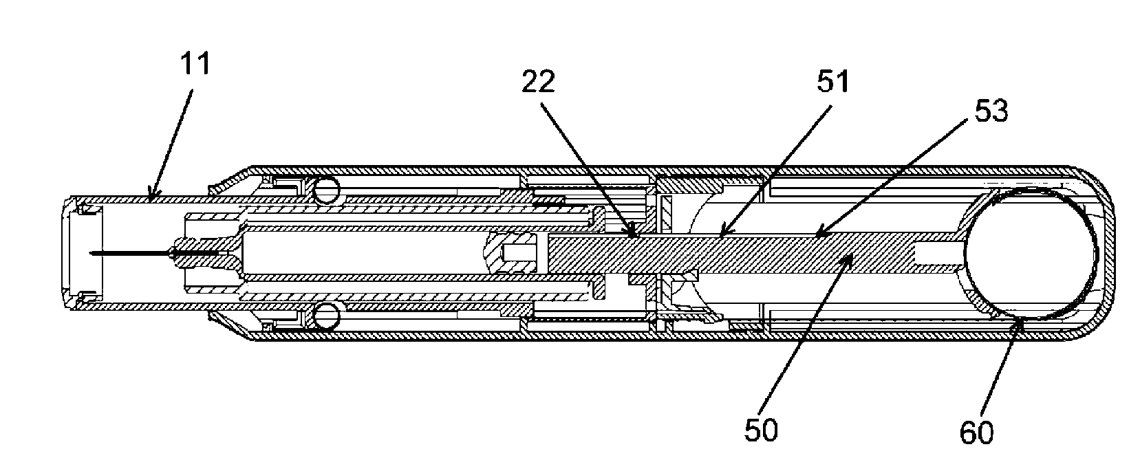
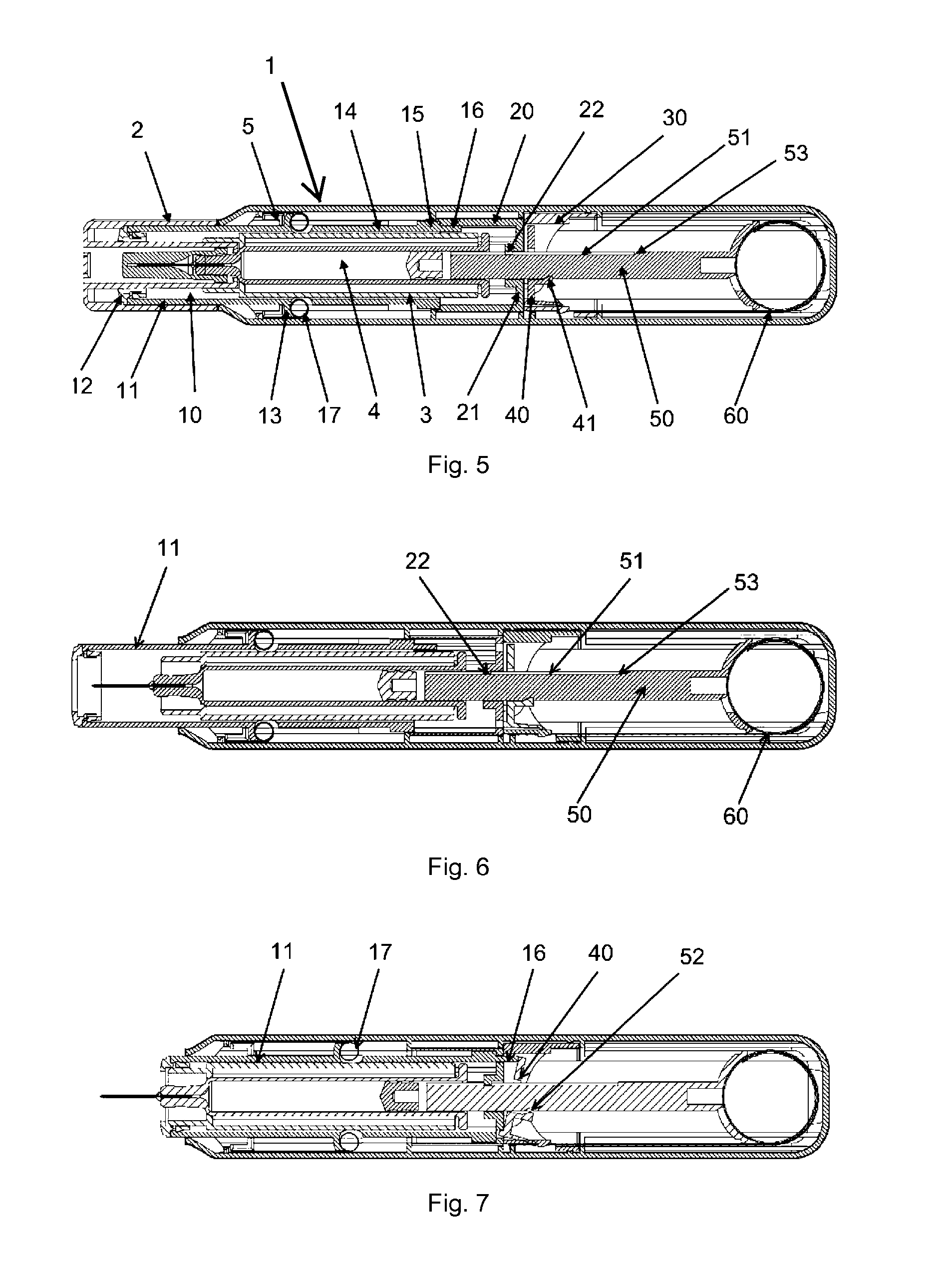
[0031]In the present application, when the term “distal part / end” is used, this refers to the part / end of the delivery device, or the parts / ends of the members thereof, which under use of the delivery device, are located the furthest away from the medicament delivery site of the patient. Correspondingly, when the term “proximal part / end” is used, this refers to the part / end of the delivery device, or the parts / ends of the members thereof, which under use of the delivery device, are located closest to the medicament delivery site of the patient.

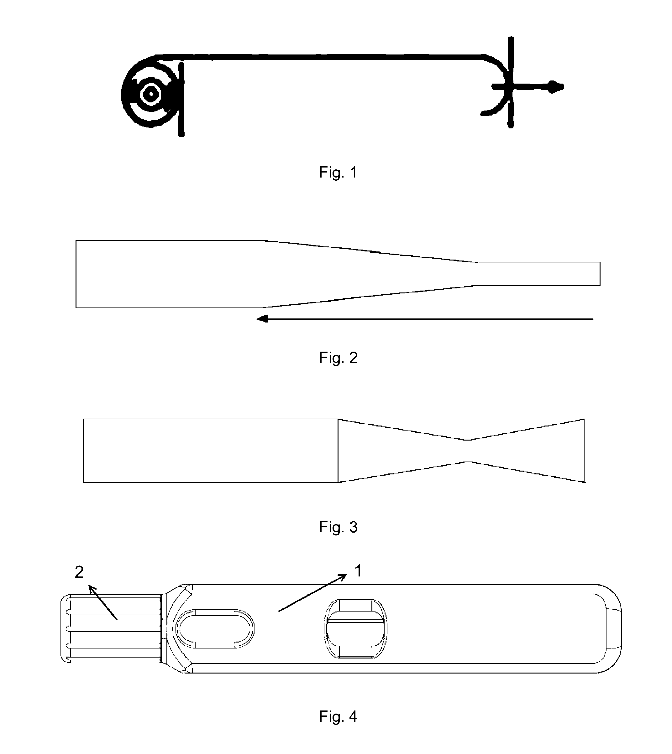
[0032]Traditional constant-force springs (CFSs) are coil springs of band material and often used when an application demands a smooth, even, uniform force through the entire expansion or contraction of the spring, e.g., the entire travel of a plunger through a container in a device for delivery of medicament e.g. an autoinjector. CFSs are commercially available from John Evans' Sons, Inc., Lansdale, Pa. 19446, USA, and Vulcan Spring & Mfg. Co....


PUM


Abstract

A device for delivery of medicament, which device comprises an elongated housing; a container (4) mounted within said housing and adapted to contain liquid medicament; a stopper slidably arranged within said container; and actuating means comprising a resilient member (60), a driving means (50) having one end connected to the stopper and a second end being operably connected to the resilient member, retaining means (40) for releasably retaining said driving means in a first position where said resilient member has an accumulated energy, and activating means operably connected to said retaining means for releasing said driving means to a second position, upon actively operation by an user, such that said accumulated energy is transferred to the driving means for driving the stopper a predetermined distance within the container whereby the medicament within said container i delivered characterized in that the resilient member is a variable force spring adapted for generating a predetermined sequence of at least two different force profiles during the medicament delivery.

Description

TECHNICAL FIELD[0001]The present invention relates to a device for the delivery of medicament to a patient. The device is adapted to be in a medicament delivery state and in a medicament non-delivery state. When the device is in a medicament delivery state, said device is adapted to drive a plunger into a container containing the medicament to be delivered, with a predetermined sequence of at least two different force profiles.BACKGROUND ART[0002]Devices for the delivery of medicament in an automatic way e.g. auto-injectors, are known as convenient and safe aids for patients to administrate various drugs themselves. For safety reasons, many devices for the delivery of medicament include covers and other devices that protect users before and after use, for example, from an injection needle. Although different devices for the delivery of medicament vary in their total feature sets, they all have a mechanism that delivers the contents of a preloaded, prefilled container automatically, ...

Claims


Application Information

Patent Timeline
Patent Type & Authority Patents(United States)
IPC IPC(8): A61M5/20A61M5/315
CPCA61M5/2033F16F1/027F16F1/10A61M5/31515A61M5/3155A61M5/31563A61M5/31591A61M5/326A61M5/46A61M2005/2013
Inventor GUILLERMO, CARLOSGIAMBATTISTA, LUCIODESALVO, DAVID
Owner SHL MEDICAL AG
Why Eureka
Try Eureka