Light source apparatus, light irradiating apparatus provided with same light source apparatus, image reading apparatus provided with same light irradiating apparatus, and image forming apparatus provided with same image reading apparatus

a technology of light irradiation and light source, which is applied in the direction of instruments, lighting support devices, and sensing by electromagnetic radiation, can solve the problems of light brightness unevenness, and achieve the effect of suppressing light brightness and simple configuration

Active Publication Date: 2013-06-11
SHARP KK
View PDF11 Cites 0 Cited by
  • Summary
  • Abstract
  • Description
  • Claims
  • Application Information

AI Technical Summary

Benefits of technology

[0012]The present invention was made in view of such circumstances, and it is an object thereof to provide a light source apparatus employing a light-emitting diode as a light source and having the effect that unevenness in light brightness is suppressed with a simple configuration, a light irradiating apparatus provided with the light source apparatus, an image reading apparatus provided with the light irradiating apparatus, and an image forming apparatus provided with the image reading apparatus.
[0017]Therefore, light brightness unevenness is suppressed for the irradiating light as a whole in the above light source apparatus. Also, the above light source apparatus has a simple structure in which the light-emitting elements are disposed at intervals in a line on the substrate.
[0021]By adopting such a configuration, reflection is promoted for light irradiated from both end peripheral portions of the light-emitting face of the light-emitting elements. Accordingly, it is possible to strengthen irradiating light that includes direct light and substrate-reflected light resulting from emitted light from both end peripheral portions of the light-emitting face.
[0022]Therefore, the brightness of irradiating light resulting from emitted light from both end peripheral portions of the light-emitting face can be brought near the brightness of irradiating light that is mainly direct light from the center portion of the light-emitting face of the light-emitting elements, so it is possible to suppress brightness unevenness of light of the light source apparatus.
[0026]Therefore, by using white as the color of the resist layer, it is possible to further increase the light reflectivity of the white light reflection promoting area formed thereon.
[0032]With the light irradiating apparatus provided with two light source apparatuses configured in this manner, it is possible to strengthen irradiating light compared to a light irradiating apparatus provided with one light source apparatus.

Problems solved by technology

Therefore, there is a tendency for brightness unevenness to occur in the light with which the original is irradiated.

Method used


Image

  • Light source apparatus, light irradiating apparatus provided with same light source apparatus, image reading apparatus provided with same light irradiating apparatus, and image forming apparatus provided with same image reading apparatus
  • Light source apparatus, light irradiating apparatus provided with same light source apparatus, image reading apparatus provided with same light irradiating apparatus, and image forming apparatus provided with same image reading apparatus
  • Light source apparatus, light irradiating apparatus provided with same light source apparatus, image reading apparatus provided with same light irradiating apparatus, and image forming apparatus provided with same image reading apparatus

Examples


Embodiment Construction

[0054]Hereinafter, a light source substrate (light source apparatus), an illumination unit (light irradiating apparatus) provided with the light source substrate, an image reading apparatus provided with the illumination unit, and an image forming apparatus provided with the image reading apparatus according to an embodiment of the present invention are described in detail with reference to the accompanying drawings.

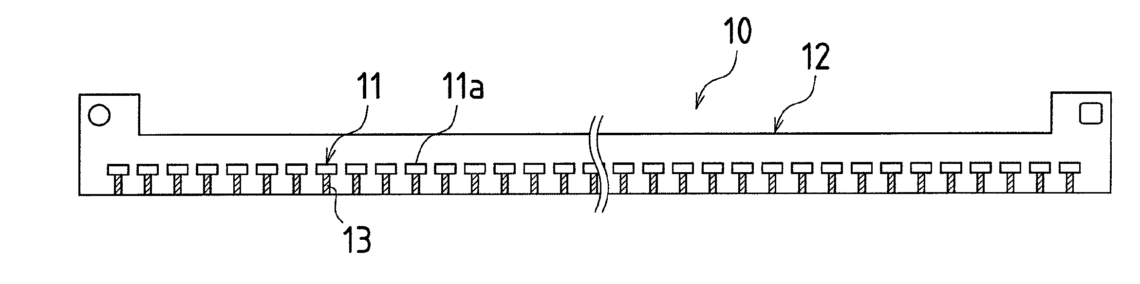
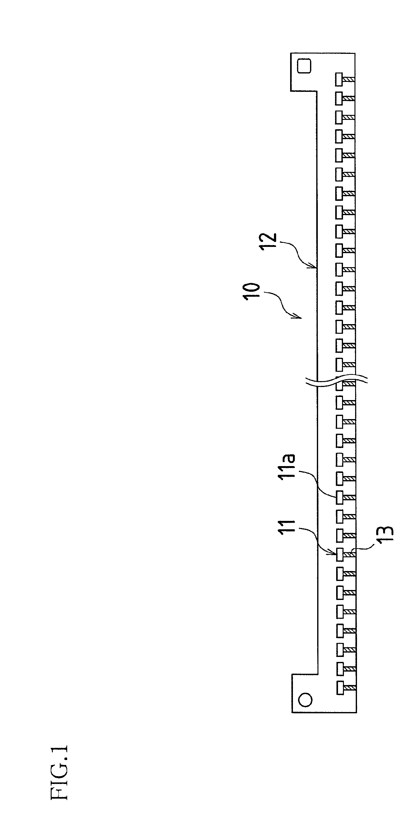
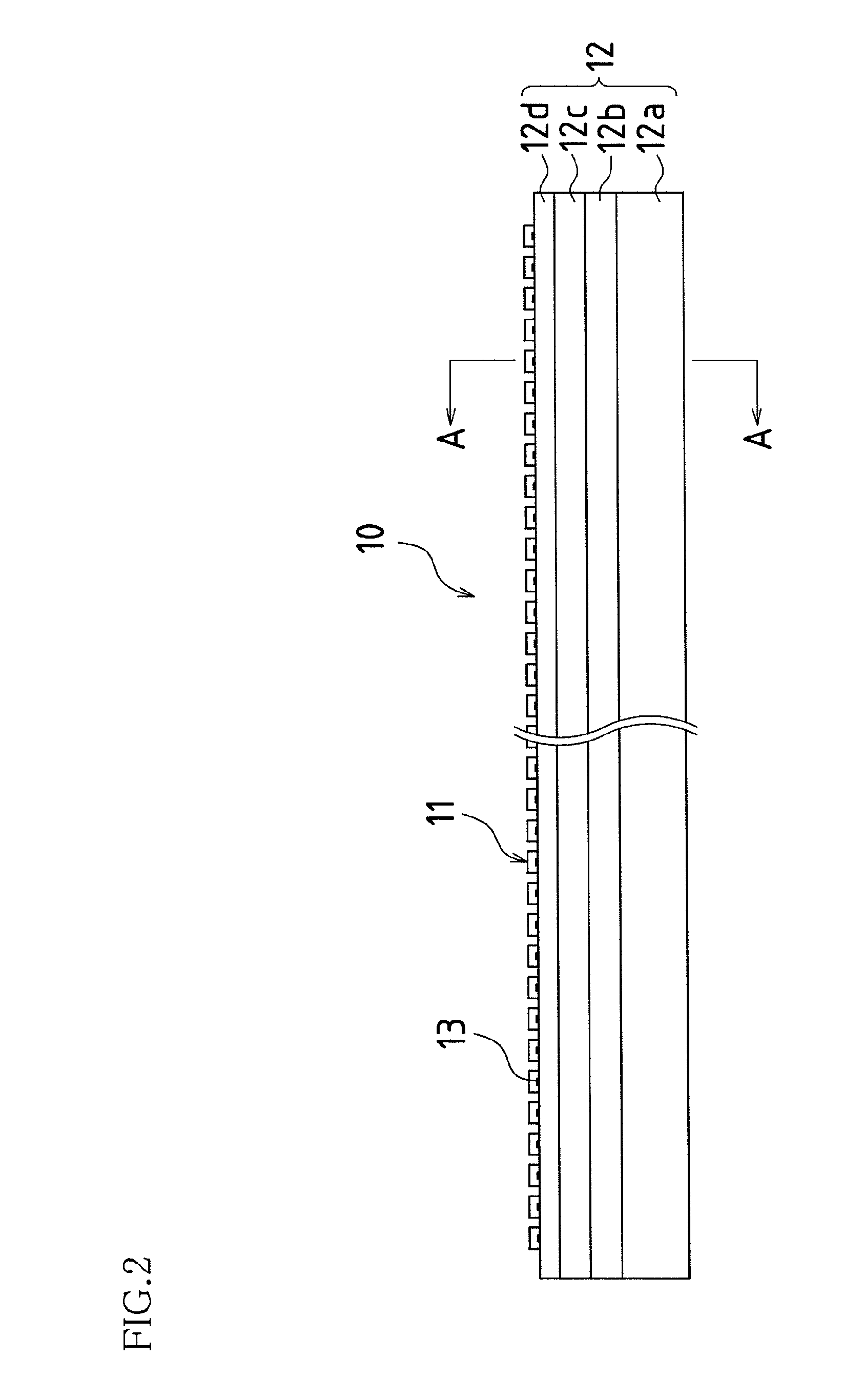
[0055]First is a description of the light source substrate in the present embodiment. The light source substrate in the present embodiment corresponds to the above-described light source apparatus. FIG. 1 is a plan view of a light source substrate 10 in the present embodiment, FIG. 2 is a front view thereof, FIG. 3 is a cross-sectional view taken along line A-A in FIG. 2, and FIG. 4 is an enlarged view of part of FIG. 1. In FIGS. 1 to 4, the light source substrate 10 is configured with light-emitting diodes 11 and a substrate 12.

[0056]Herein, as shown in FIGS. 2 and 3, t...


PUM


Abstract

In one embodiment of a semiconductor apparatus of the present invention, a plurality of light-emitting elements provided with a light-emitting face are disposed at intervals in a line on a surface of a substrate, and serve as a light source apparatus that emits irradiating light forward from the light-emitting face along the surface of the substrate, and on a forward side of the light-emitting face in the surface of the substrate, a light reflection suppression area is formed extending forward with a width less than the width of the light-emitting face from a lower edge of the light-emitting face.

Description

CROSS-REFERENCE TO RELATED APPLICATION[0001]This application claims priority on Patent Application No. 2009-119108 filed in Japan on May 15, 2009, the entire contents of which are herein incorporated by reference.BACKGROUND OF THE INVENTION[0002]The present invention relates to a light source apparatus having a plurality of light-emitting elements disposed in a line, a light irradiating apparatus provided with the light source apparatus, an image reading apparatus provided with the light irradiating apparatus, and an image forming apparatus provided with the image reading apparatus.[0003]An image forming apparatus such as a copy machine or a facsimile machine is provided with an image reading apparatus in order to read an image of an original. This image reading apparatus is ordinarily configured with an original placement plate, an original pressing plate, an illumination unit (light irradiating apparatus), and a photoelectric converter.[0004]Herein, the original placement plate is...

Claims


Application Information

Patent Timeline
Patent Type & Authority Patents(United States)
IPC IPC(8): H04N1/04G01D11/00G06K7/10H01L27/00H01L29/20H01L33/00F21V1/00H04N1/46F21V9/00
CPCH04N1/02815H04N1/02865H04N1/02885H04N1/02895
Inventor IMOTO, MASAHIROYOSHIMOTO, MITSUHARUSUTO, YASUHIROFUKUTOME, SHOHICHIYAMANAKA, HISASHI
Owner SHARP KK
Why Eureka
Try Eureka