Firearm system for data acquisition and control

Inactive Publication Date: 2013-06-18
MCRAE MICHAEL WILLIAM
View PDF30 Cites 57 Cited by
  • Summary
  • Abstract
  • Description
  • Claims
  • Application Information

AI Technical Summary

Problems solved by technology

This is particularly bad when one's life is at stake.
Conversely, users thinking that a firearm is not ready to fire, pick up a firearm and cause an accidental discharge.
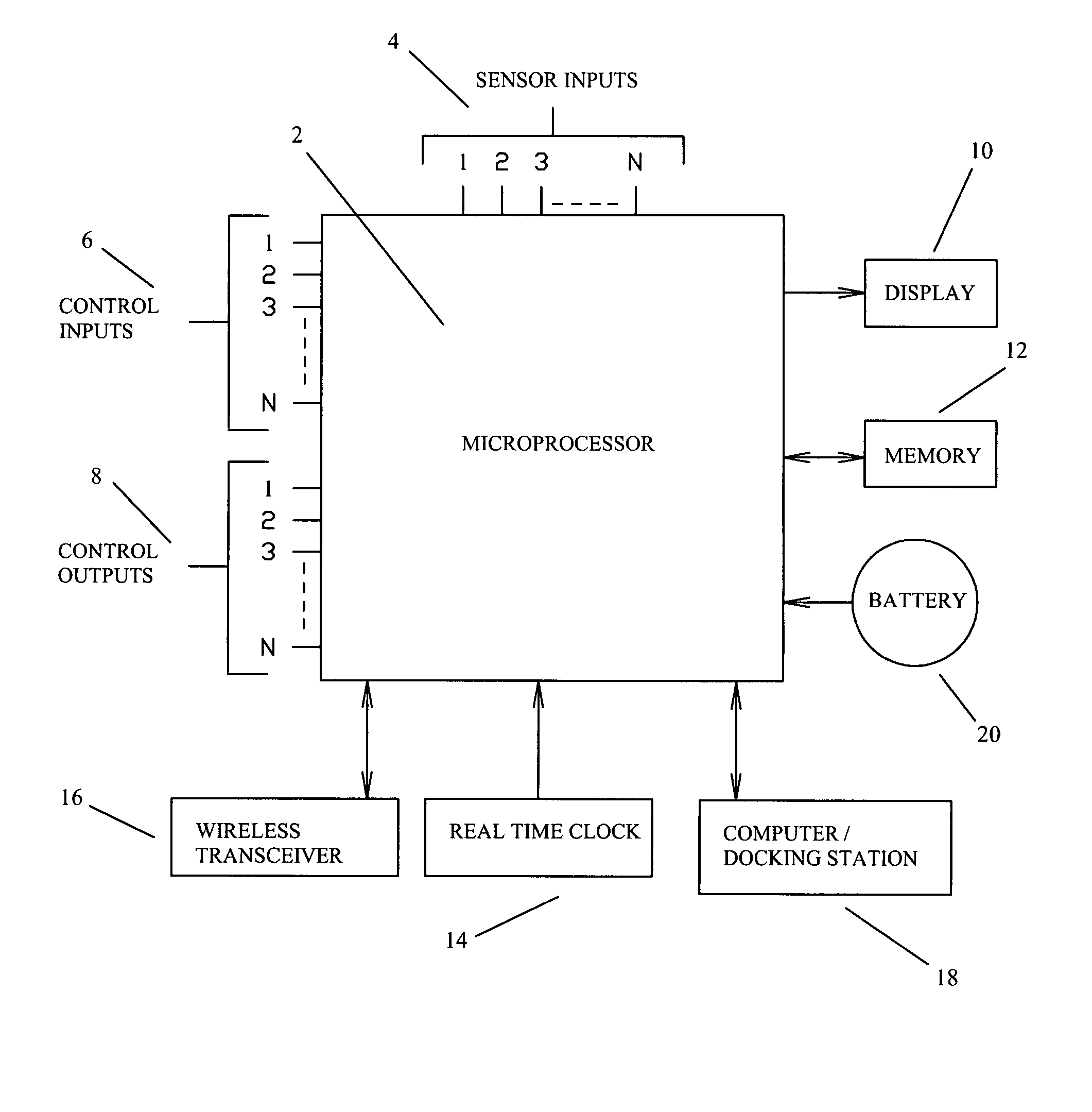
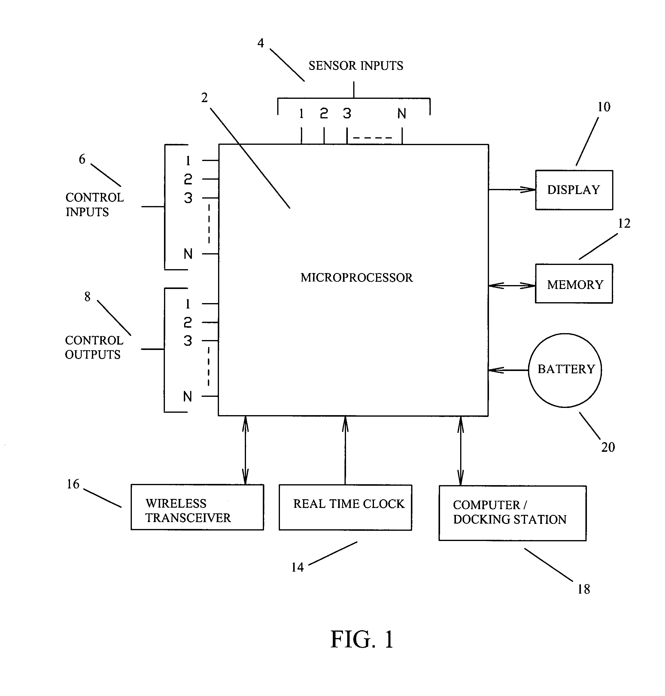
Additionally, the firearm system could notify the user as to how many rounds are available in the firearm.
However this requires additional equipment to be purchased and set-up by the user, and is not conveniently located in or on the firearm itself.
However, this invention suffers from the following limitations:Does not take advantage of electronics embedded into the rifle scope.Is unable to measure the actual bullet velocity (no bullet chronograph).Cannot measure the actual distance to target.Is unable to determine actual bullet drop compensations due to missing chronograph.Requires equipment outside of the rifle & scope combination in order to understand the reticle spatial relationships.The reticle is fixed and unable to be electronically adjusted.Requires the user to perform confusing mental gymnastics in order to mentally superimpose the ballistics table onto the fixed reticle.
Once the range-to-target is obtained, the on-board microprocessor calculates the required bullet-drop-compensation, and adjusts a compensation cross-hair [It should understood that this is a very difficult patent to understand, and arguably does not contain adequate information for one skilled in the art to understand and build such an item.
In either case however, the numeric display is obviously not in direct alignment with the scope optics.
This presents obvious challenges for the user.
Additionally, this ignition system is not applicable to traditional mechanically fired firearms.
Although an interesting invention, this device is not capable of having a dynamically adjusted reticle, as the reticle is permanently etched on the device optics.
This is not always the case and can cause false readings.
This is an obvious danger as a user may think the firearm is unloaded when it actually isn't.
However, this invention suffers from the following shortcomings:Is unable to provide continued operation of the paintball gun when the battery dies, or if the electronics otherwise fail.Is unable to determine if the paintball gun has a loaded chamber.Is unable to determine how many shots remain in the paintball gun.Is unable to determine if the paintball gun is cocked.Is unable to determine the position of the paintball gun safety mechanism.Is unable to provide the “Go / No-Go” ready status (loaded chamber, cocked, safety off) of the paintball gun.Is unable to measure the efficiency of the paintball gun mechanical action.Is unable to differentiate between operating the paintball gun mechanical action by hand, or by discharging the paintball gun.Is unable to combine the above information and interpret whether or not the paintball gun has been discharged.Is unable to differentiate between a “dry-fire” trigger-pull, and actually discharging the paintball gun.Is unable to determine with what velocity a paintball was discharged (no paintball chronograph).Is unable to differentiate between cleaning the paintball gun barrel, and taking a chronograph reading.Is unable to measure the distance to target.Is unable to combine the paintball velocity and distance to target information to calculate “paintball drop” compensation.Is unable to adjust the reticle on an optical scope to correspond with the “paintball drop” compensation.Is unable to cradle the paintball gun in a docking-station.Is unable to be remotely controlled by a “command and control” center.
Further, the microprocessor may time stamp these events as they happen.

Method used


Image

  • Firearm system for data acquisition and control
  • Firearm system for data acquisition and control
  • Firearm system for data acquisition and control

Examples


Embodiment Construction

FIGS. 1 through 15

[0105]FIG. 1 through FIG. 15 depict specific preferred embodiments of the present invention for purposes of illustration only. One skilled in the art will recognize from the following discussion that alternative embodiments of the structures and methods illustrated herein may be employed without departing from the invention.

[0106]Now referring to FIG. 1; This diagram depicts a typical architecture of the firearm system. The focal point of the architecture is the microprocessor 2. Here the microprocessor communicates with and / or controls the firearm system. The microprocessor receives sensory data through sensor inputs 4. The sensors associated with these inputs are located on the firearm itself, and will be discussed in later figures.

[0107]The microprocessor will also receive user data and commands through control inputs 6. These inputs may come from buttons, knobs, or keypads that are also located on the firearm itself. The microprocessor may also be equipped with...


PUM


Abstract

A microprocessor circuit that is used to monitor and control a firearm. The microprocessor circuit accomplishes this by monitoring various sensor & control inputs, and acting on these inputs to execute user defined functions. The microprocessor circuit can use the sensory input to determine firearm statistics. These statistics can include the number of times the firearm has been shot, the efficiency of the firearm automatic action, range-to-target, and etcetera. The firearm system can also use a combination of sensors to fabricate a bullet chronograph whereby the muzzle velocity of a cartridge can be determined. These statistics can be date-stamped and recorded into memory. Statistics from Law Enforcement firearms can be used for courtroom evidence and police reporting. These statistics can also be used for firearm maintenance and warranty repair. The microprocessor circuit can display the statistical data to the user via simple light emitting diodes, or sophisticated liquid crystal displays. Data can also be downloaded to a computer docking station as well. The microprocessor circuit can also display the information within the optics of a riflescope. When used in conjunction with a laser range finder sensor, the microprocessor circuit can adjust the electronic cross-hairs (reticle) to compensate for the bullet trajectory.

Description

CROSS-REFERENCE TO RELATED APPLICATIONS[0001]This application claims the benefit of Provisional Patent Application;[0002]Ser. No.: 60 / 802,677[0003]Filed: May 23, 2006FEDERALLY SPONSORED RESEARCH[0004]Not ApplicableSEQUENCE LISTING OR PROGRAM[0005]Not ApplicableBACKGROUND OF THE INVENTION[0006]1. Field of Invention[0007]This invention relates to firearms; specifically to an electronic system for gathering firearm data, manipulating such data, displaying data to the user, receiving commands from the user, recording pertinent information to memory, and finally for controlling the firearm itself.[0008]2. Description of Prior Art[0009]Firearms are used for self-defense, hunting, marksmanship competition, law enforcement, and the military. Although the field of firearms is very mature, modern electronics now provide a way to expand the field of firearms even further.[0010]In much the same way that a car's computer interfaces with the user; a firearm system can collect data associated with...

Claims


Application Information

Patent Timeline
Patent Type & Authority Patents(United States)
IPC IPC(8): F41A9/53F41A17/00F41G1/38
CPCF41A17/06F41G1/38F41A9/53G06F1/1632G01S17/88
Inventor MCRAE, MICHAEL WILLIAM
Owner MCRAE MICHAEL WILLIAM
Why Eureka
Try Eureka