Battery mounting structure of electromotive vehicle

a technology of electromotive vehicles and mounting structures, which is applied in the direction of electric/fluid circuits, cell components, propulsion parts, etc., can solve the problems of increasing the assembling cost, increasing the manufacturing cost of battery modules, and deteriorating the process of battery modules to the vehicle, so as to achieve efficient arrangement of plural battery modules

Inactive Publication Date: 2013-06-18
MAZDA MOTOR CORP
View PDF6 Cites 50 Cited by
  • Summary
  • Abstract
  • Description
  • Claims
  • Application Information

AI Technical Summary

Benefits of technology

[0008]The present invention has been devised in view of the above-described matters, and an object of the present invention is to provide a battery mounting structure of an electromotive vehicle which can efficiently arrange the plural battery modules, thereby mount as many battery modules as possible.

Problems solved by technology

However, if the plural battery modules mounted on the vehicle have different shapes from each other, the manufacturing costs of the battery modules may increase, and the mount processes of the battery modules to the vehicle may deteriorate, thereby increasing the assembling costs as well.
Meanwhile, in case all of the battery modules having the same shape are arranged in the same direction like the structure disclosed in the above-described publication, the mount space of the battery modules below the rear floor portion may not be utilized properly.
Herein, while US Patent Application Publication No. 2011 / 0024207 discloses a cooling structure for the electromotive vehicle equipped with the battery modules, the above-described problem of the battery mount has not been solved by the structure disclosed in this patent document.

Method used


Image

  • Battery mounting structure of electromotive vehicle
  • Battery mounting structure of electromotive vehicle
  • Battery mounting structure of electromotive vehicle

Examples


Embodiment Construction

[0037]Hereafter, a preferred embodiment of the present invention will be descried.

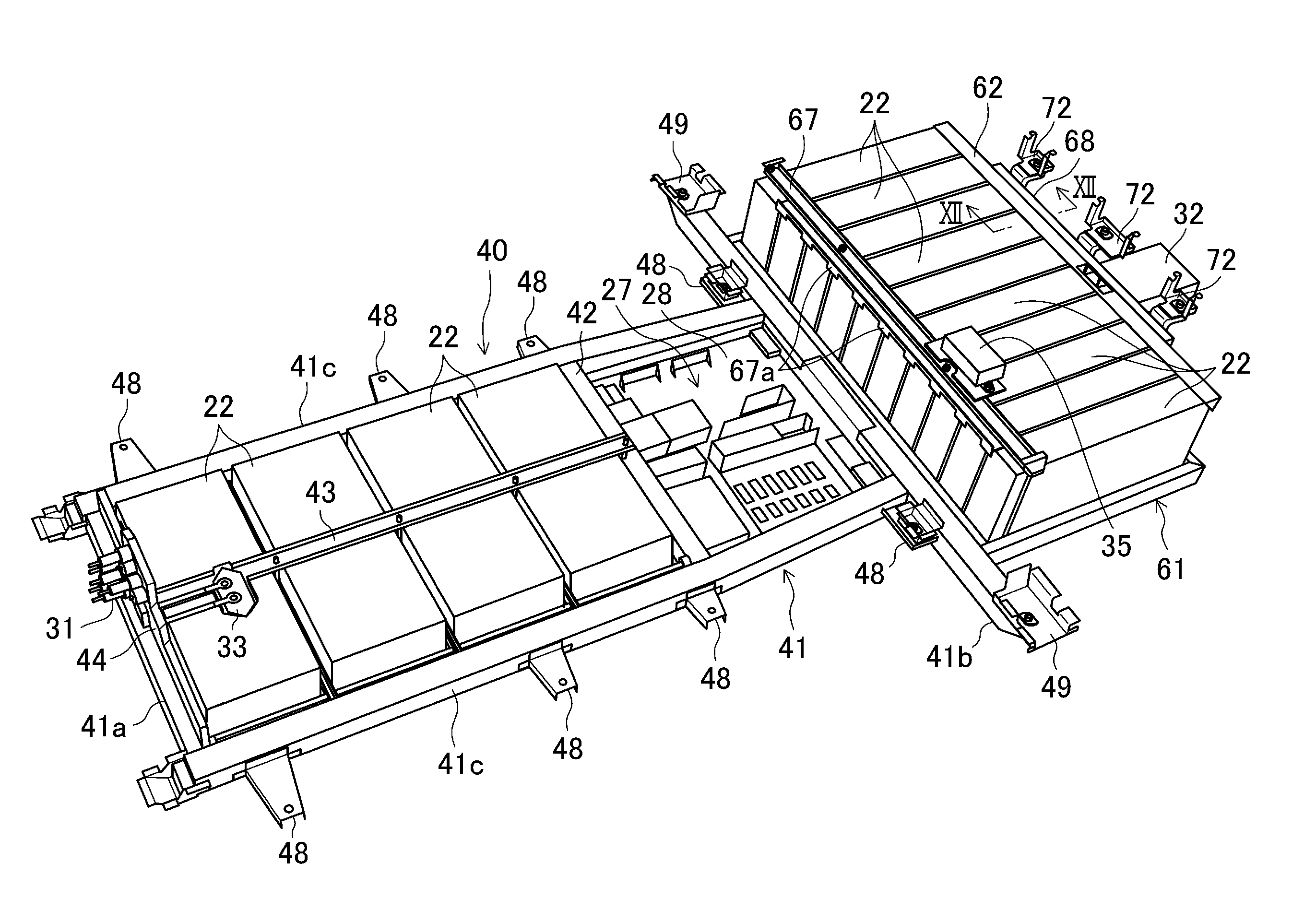
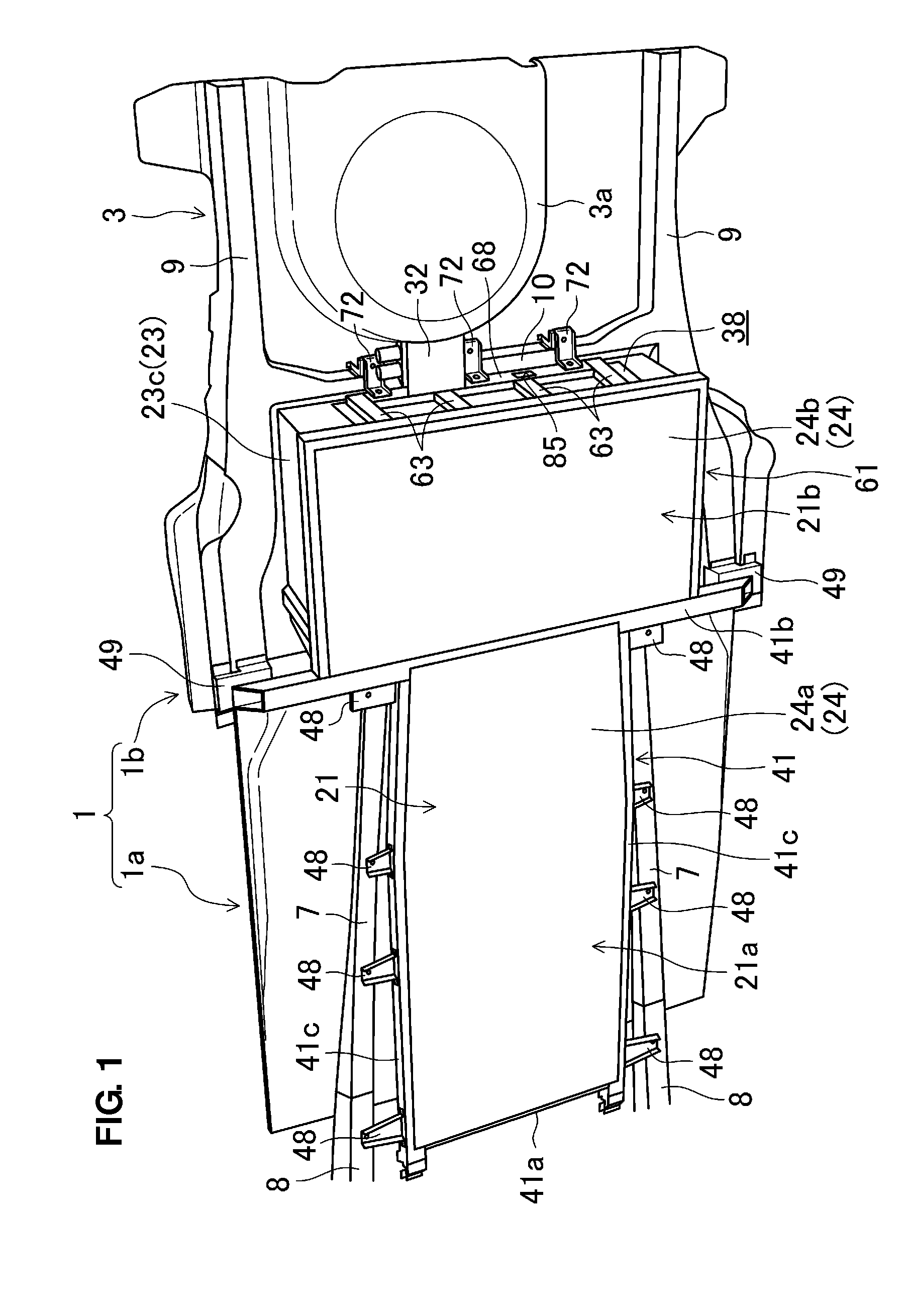
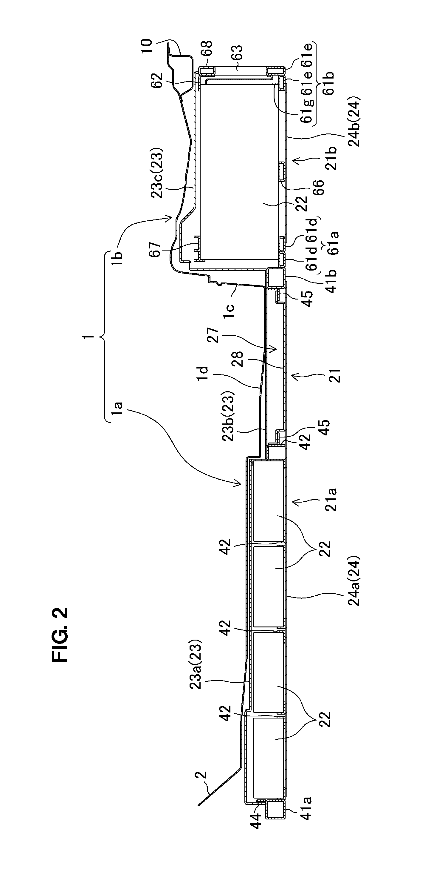
[0038]FIGS. 1 and 2 show a lower-side vehicle floor 1 of an electromotive vehicle (an electric vehicle in the present embodiment) which is equipped with a battery mount structure according to the present embodiment of the present invention. Herein, the front, rear, left, right, above, or below with respect to a vehicle will be simply referred to as the “front”“rear”“left”“right”“above” or “below.”

[0039]The vehicle floor 1 comprises a front floor portion 1a and a rear floor portion 1b which is located above the level of the front floor portion 1a. That is, a kick-up portion 1c is formed between the front floor portion 1a and the rear floor portion 1b, and the level of the rear floor portion 1b is higher than the front floor portion 1a by the height of this kick-up portion 1c.

[0040]A rear seat (not illustrated) is arranged on the rear floor portion 1b. A foot place 1d for a passenger seated in the rear ...


PUM


Abstract

Plural battery modules mounted on a first mount portion of a battery unit which is positioned below a front floor portion are arranged in a vehicle longitudinal direction such that the longitudinal direction of each of the battery modules matches a vehicle width direction and the short side of a rectangular section of each of the battery modules extends in a vehicle vertical direction, and plural battery modules mounted on a second mount portion which is positioned below a rear floor portion are arranged in the vehicle width direction such that the longitudinal direction of each of the battery modules matches the vehicle longitudinal direction and the long side of the rectangular section of each of the battery modules extends in the vehicle vertical direction. Accordingly, the plural battery modules can be arranged efficiently.

Description

BACKGROUND OF THE INVENTION[0001]The present invention relates to a battery mounting structure of an electromotive vehicle, in which plural battery modules having substantially the same shape are mounted below a vehicle floor as a unit.[0002]In general, plural battery modules are mounted below a vehicle floor as a unit in an electromotive vehicle, such as an electric automotive vehicle. Japanese Patent Laid-Open Publication No. 2009-248708, for example, discloses a structure in which the plural battery modules are mounted in the almost whole area below the vehicle floor and on the rear suspension via the tray. In this structure, the plural rectangular-parallelepiped-shaped battery modules having the rectangular section along their longitudinal direction are arranged in both the vehicle longitudinal and width directions such that the longitudinal direction of each of the battery modules matches the vehicle longitudinal direction and the short side of the rectangular section of each o...

Claims


Application Information

Patent Timeline
Patent Type & Authority Patents(United States)
IPC IPC(8): B60K1/04
CPCB60K1/04B60K2001/0438
Inventor USAMI, IKUOKITA, HIROKAZUNOMURA, HIROYUKISADAHIRA, SEIJI
Owner MAZDA MOTOR CORP
Why Eureka
Try Eureka