Eureka AIR delivers breakthrough ideas for toughest innovation challenges, trusted by R&D personnel around the world.

Electronic control device

a control device and electronic technology, applied in the direction of control/drive circuits, circuit bendability/stretchability, mechanical energy handling, etc., can solve the problems of circuit board as a whole being subject to a limitation on mounting layout and wiring layout of electronic components, and suppress the increase in complexity of wiring layout. , to achieve the effect of efficient arrangement of electronic components

Active Publication Date: 2020-10-08
HITACHI ASTEMO LTD
View PDF0 Cites 3 Cited by
  • Summary
  • Abstract
  • Description
  • Claims
  • Application Information

AI Technical Summary

Benefits of technology

The present invention is a multilayer wiring board with flexible sections between components mounting sections, where a detecting element and detection signal lines are arranged to detect the operating state of an electric actuator. The electronic component group and CPU are arranged along the detection signal lines to efficiently arrange them while suppressing wiring complexity. The technical effect is the arrangement of electronic components forming a control system for the electric actuator in an efficient and organized manner.

Problems solved by technology

In a case of the circuit board having such bending section, since the bending section formed partly thin is interposed between the rigid board sections, there is a risk that the circuit board as a whole will be subject to a limitation on a mounting layout and a wiring layout of electronic components.
That is, there is a problem of how the mounting layout and the wiring layout of the electronic components including a detecting element such as a rotation sensor that detects an operating state of an electric actuator in a control system of the electric actuator should be determined.

Method used


Image

  • Electronic control device
  • Electronic control device
  • Electronic control device

Examples


Embodiment Construction

[0017]An embodiment in which the present invention is applied to, for instance, a control device of an electric power steering device of a vehicle will be explained in detail below with reference to the drawings.

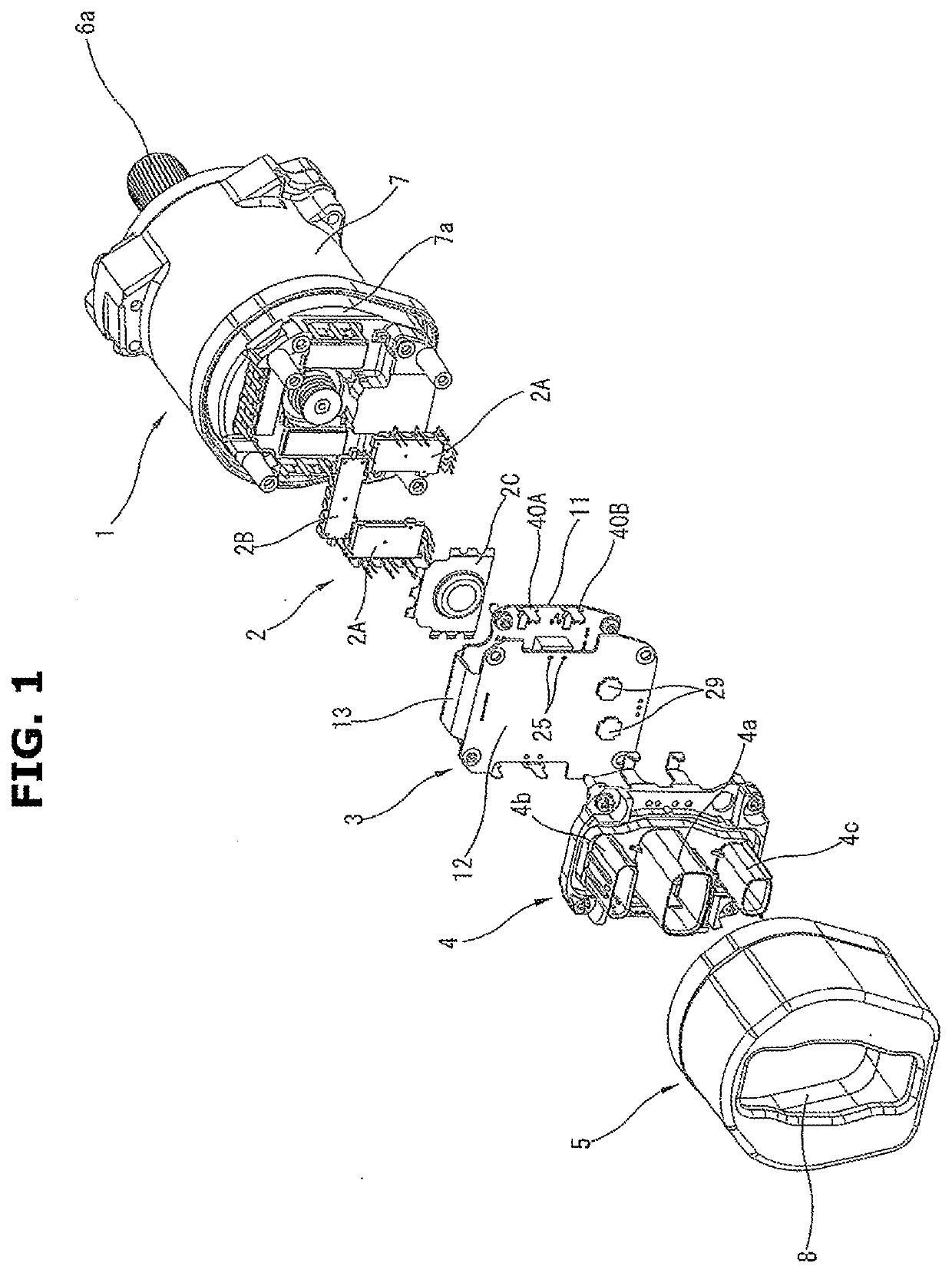
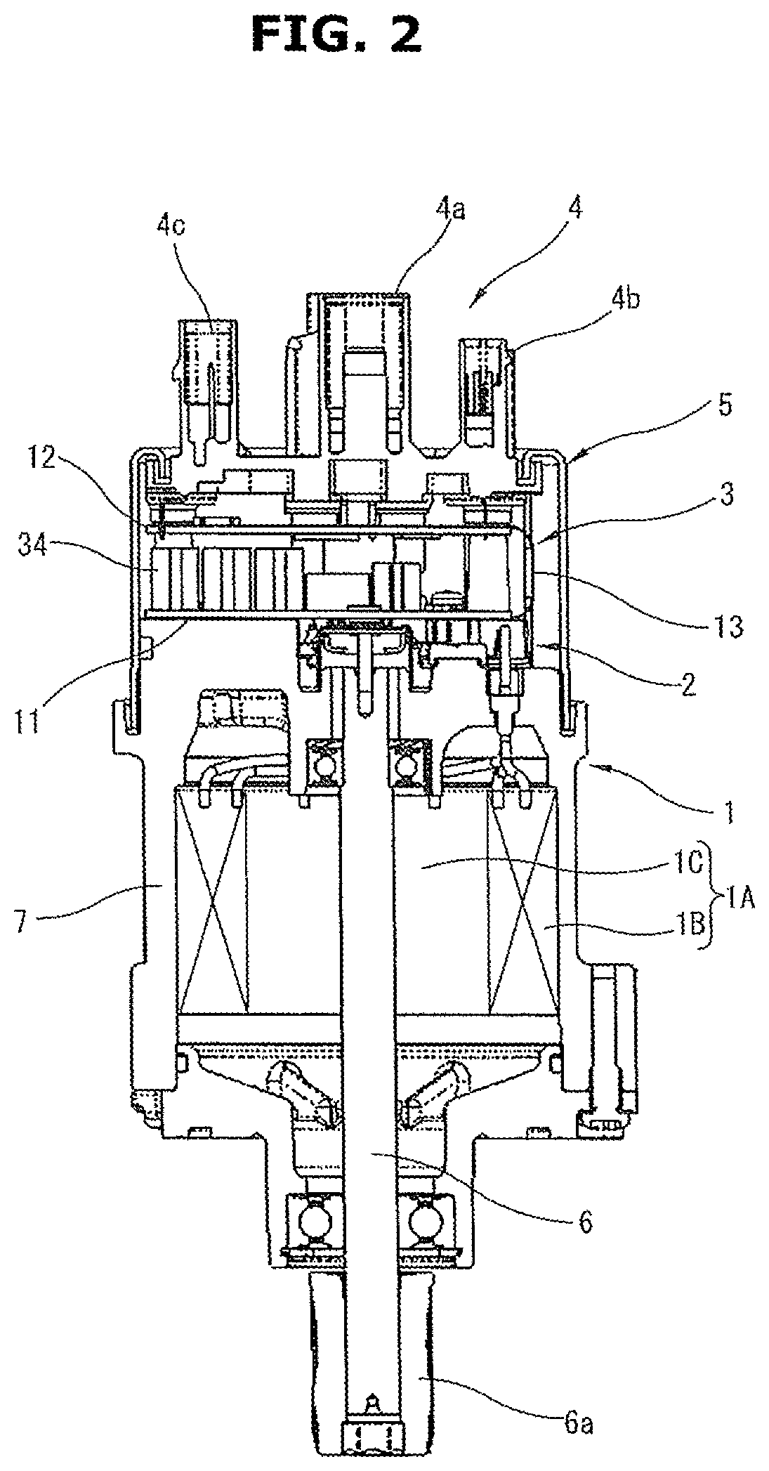
[0018]FIG. 1 is a perspective exploded view of an electric actuator device that provides a steering assist force to a steering mechanism (not shown) of an electric power steering device. FIG. 2 is a sectional view of the electric actuator device. This electric actuator device has a cylindrical motor unit 1, an inverter / power module 2, a circuit board 3 formed by a foldable multilayer wiring board which is the embodiment of the present invention, a connector member 4 where a plurality of connectors are integrated and a motor cover 5 fixed to one end portion of the motor unit 1 so as to cover or accommodate the inverter / power module 2, the circuit board 3 and the connector member 4.

[0019]The motor unit 1 is a unit configured such that a motor 1A (see FIG. 2), which corresponds...


PUM


Abstract

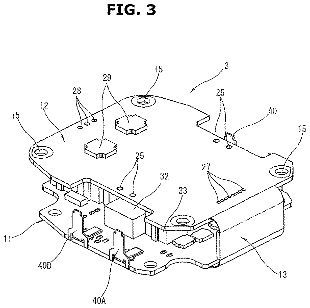
A wiring board (3) has first and second rigid sections (11, 12) each having six metal leaf layers, and a flexible section (13) having two metal leaf layers that connect the both rigid sections (11, 12). A capacitor unit (34) and a filter unit 31, which supplies power to an inverter, are mounted on the first rigid section (11), and a CPU (21) and a pre-driver circuit element (22) are mounted on the second rigid section (12). Mutually-independent two control systems are arranged so as to be symmetrical about a board center line (M). Detection signal lines (51) of rotation sensors (37, 38) located at the middle of the first rigid section (11) extend along the board center line (M) on the flexible section (13). Each of the two control systems is configured along a wiring direction of the detection signal lines (51).

Description

TECHNICAL FIELD[0001]The present invention relates to an electronic control device using a foldable multilayer wiring board that can be assembled in a housing with the multilayer wiring board being bent.BACKGROUND ART[0002]Patent Document 1 discloses, as a circuit board mounted in a motor unit of a power steering device, a circuit board that can be used with the circuit board being folded into a substantially U-shape by coupling a plurality of rigid board sections through a flexible bending section that is thinner than the rigid board sections.[0003]In a case of the circuit board having such bending section, since the bending section formed partly thin is interposed between the rigid board sections, there is a risk that the circuit board as a whole will be subject to a limitation on a mounting layout and a wiring layout of electronic components. That is, there is a problem of how the mounting layout and the wiring layout of the electronic components including a detecting element suc...

Claims


Application Information

Patent Timeline
Patent Type & Authority Applications(United States)
IPC IPC(8): H02K11/33H05K1/02
CPCH02K11/33H05K1/028H02K7/14H02K2211/03H02K5/225H02K11/21H02K29/06H05K1/0278H05K1/189H05K3/4691H02K11/30
Inventor TATEYAMA, TETSUROUYOSHINAGA, KUMIKOICHIKAWA, EIJIWATANABE, HIROFUMITAKAHASHI, MOTOTAKA
Owner HITACHI ASTEMO LTD
Why Eureka
Eureka Blog
Learn More