Fast vision system

a vision system and fast technology, applied in the field of machine vision systems, can solve the problems of requiring a large amount of time (, tens of milliseconds) per image iteration, and the solution is not fast enough for other applications, and achieve the effect of no cos

Active Publication Date: 2013-06-18
COGNEX CORP
View PDF10 Cites 2 Cited by
  • Summary
  • Abstract
  • Description
  • Claims
  • Application Information

AI Technical Summary

Benefits of technology

[0010]It has been recognized that high speed processors can be used to expedite the overall process of obtaining an in-focus image and performing a vision process on the image by processing images in parallel with obtaining other images at different focus positions. For instance, in some cases where a camera lens has a range of focus positions from a minimum position to a maximum position, the lens and camera sensor may be controlled to obtain a sequence of images in rapid succession with the lens focused at all different pre-determined (i.e., image independent) useful focus positions. After each image is obtained and in parallel with obtaining additional images, the obtained image is processed in some fashion to expedite the overall vision process. For instance, in some cases the obtained image may be processed to attempt to find a symbol or item feature in the image while additional images at different predetermined useful focus positions are obtained. In other cases the image may be processed to attempt to decode a symbol therein while additional images at different focus positions are obtained. Here, with an extremely fast processor there is no cost to processing images that are out of focus and the system may be able to sweep through all useful focus positions in 100 milliseconds or less obtaining and processing all useful images in rapid succession.
[0011]In other cases a processor may essentially run separate software threads where one thread handles iterative focusing and another thread simultaneously attempts to decode or find a symbol in every acquired image (i.e., in the differently focused images). With a fast processor there is no performance cost associated with processing out of focus images and, in some cases, useful information such as symbol location in the image, partially decoded data, etc., may be obtained from a slightly blurred image prior to obtaining a precisely focused image.
[0016]Some embodiments include a method for facilitating a machine vision process using a camera having a multi-focus lens having a lens field of view, the method comprising the steps of (a) positioning at least one of the camera and an item to be imaged so the lens field of view is directed at the item to be imaged, (b) setting the lens at a focus position, (c) obtaining an image of the item with the lens at the focus position, (d) attempting to perform the machine vision process on the image and (e) while performing step (d), initiating steps (b) and (c) using a next focus position to obtain a next image of the item where the next focus position is different than any previous focus position.
[0022]Some embodiments include a system for facilitating a machine vision process using a camera having a multi-focus lens having a lens field of view, the system comprising a processor programmed to perform the steps of, (a) setting the lens at a focus position, (b) obtaining an image of the item with the lens at the focus position, (c) attempting to perform the machine vision process on the image and (d) while performing step (c), initiating steps (a) and (b) using a next focus position to obtain a next image of the item where the next focus position is different than any previous focus position.

Problems solved by technology

While hunting solutions work well in some applications, unfortunately these solutions are not fast enough for other applications where high speed vision processes are required or desirable.
To this end, known auto-focus systems often require a large amount of time (e.g., tens of milliseconds) per image iteration just to adjust the lens prior to obtaining a next image in addition to the time required to perform the focus determining process to analyze each acquired image to make a decision on what to do next (i.e., obtain another image using a different focus position if not in focus and to perform the vision process on the obtained image if in focus).
Unfortunately, however, range finding systems require dedicated range finding hardware in addition to other system hardware and therefore increase overall system costs.

Method used


Image

  • Fast vision system
  • Fast vision system
  • Fast vision system

Examples


Embodiment Construction

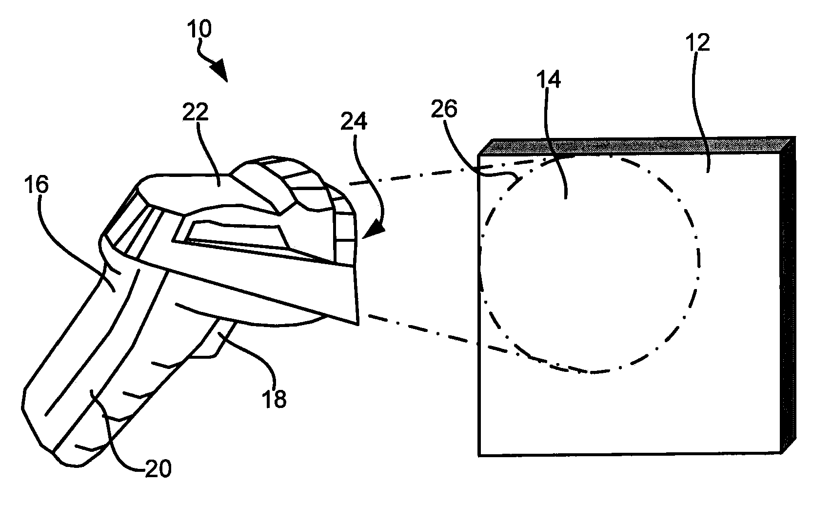
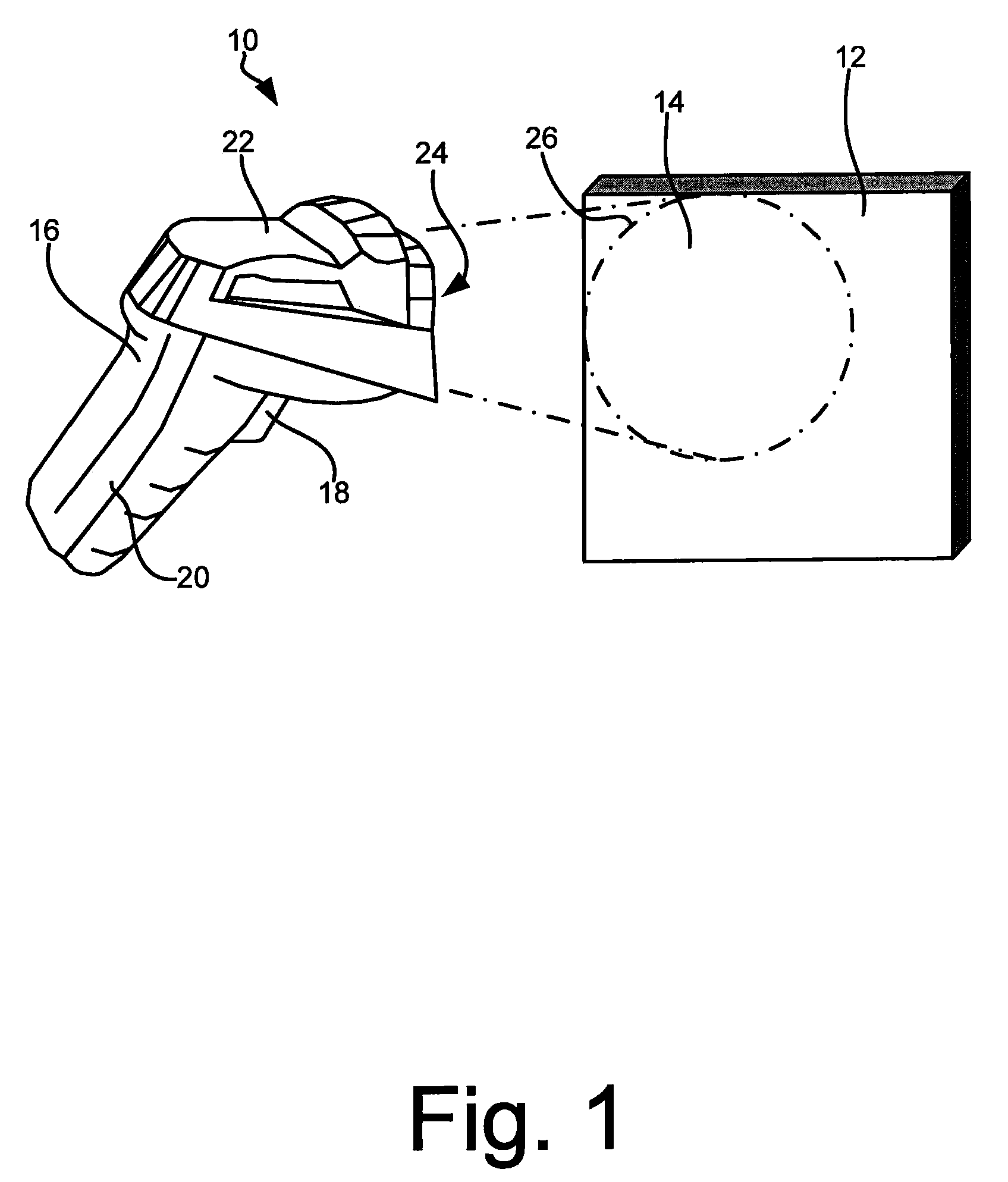
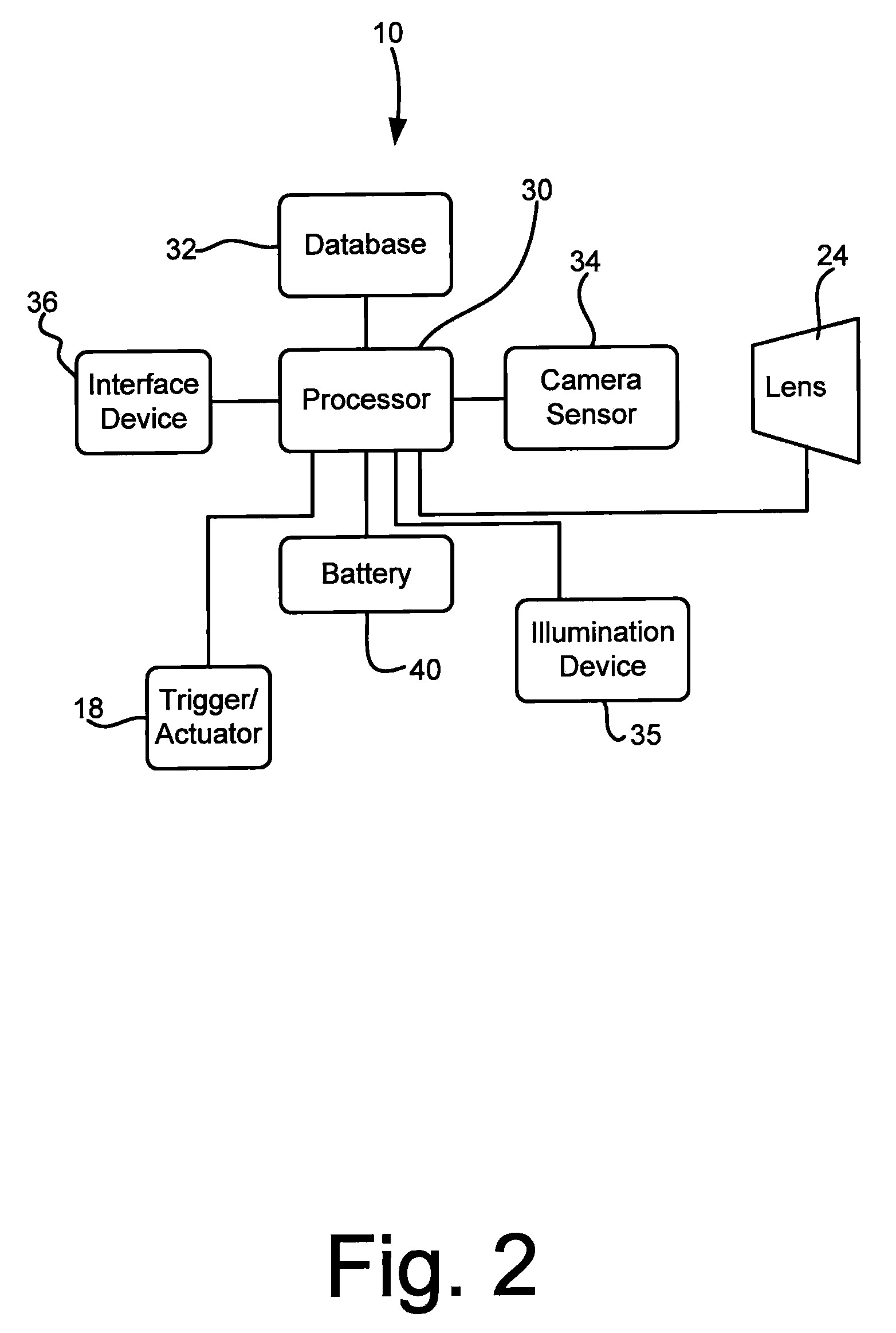
[0035]The various aspects of the subject invention are now described with reference to the annexed drawings, wherein like reference numerals correspond to similar elements throughout the several views. It should be understood, however, that the drawings and detailed description hereafter relating thereto are not intended to limit the claimed subject matter to the particular form disclosed. Rather, the intention is to cover all modifications, equivalents, and alternatives falling within the spirit and scope of the claimed subject matter.

[0036]The word “exemplary” is used herein to mean serving as an example, instance, or illustration. Any aspect or design described herein as “exemplary” is not necessarily to be construed as preferred or advantageous over other aspects or designs.

[0037]Furthermore, the disclosed subject matter may be implemented as a system, method, apparatus, or article of manufacture using standard programming and / or engineering techniques to produce software, firmw...


PUM


Abstract

A method and apparatus for performing a vision process using a camera having a multi-focus lens having a lens field of view where the lens can be set at different focus positions the method comprising the steps of positioning at least one of the camera and an item to be imaged so the lens field of view is directed at the item to be imaged, obtaining a plurality of images where each image is obtained with the lens focus at a different position and after each image is obtained, attempting to perform the machine vision process using the image irrespective of whether or not the lens was focused when the image was obtained.

Description

CROSS-REFERENCE TO RELATED APPLICATIONS[0001]Not applicable.STATEMENT REGARDING FEDERALLY SPONSORED RESEARCH OR DEVELOPMENT[0002]Not applicable.BACKGROUND OF THE INVENTION[0003]The present invention relates to machine vision systems and more specifically to a system wherein a fast processor is used to facilitate a machine vision process in parallel with obtaining images at different focus positions of a camera lens to expedite the overall vision process.[0004]Machine vision systems have been developed for many different applications. For example, vision systems have been developed for reading bar codes and other types of symbols placed on packages or products to obtain information there from. Other vision systems have been developed for inspecting manufactured parts for features / characteristics.[0005]Many vision systems include a camera for obtaining images of symbols or items to be imaged. A processor receives the images and extracts information there from which can then be used to...

Claims


Application Information

Patent Timeline
Patent Type & Authority Patents(United States)
IPC IPC(8): G06K7/14G06K7/10
CPCH04N5/2356G06K7/10544H04N5/23212G06K7/10722G06K2207/1013H04N23/67H04N23/743G06K7/10831G02B7/09
Inventor NADABAR, SATEESHAEQUITZ, WILLIAM
Owner COGNEX CORP
Why Eureka
Try Eureka