Paddle wheel electric generator

a technology of electric generator and paddle wheel, which is applied in the direction of electric generator control, machines/engines, mechanical equipment, etc., can solve the problem of general low maintenan

Inactive Publication Date: 2011-06-28
WINIUS HENRY C
View PDF17 Cites 37 Cited by
  • Summary
  • Abstract
  • Description
  • Claims
  • Application Information

AI Technical Summary

Benefits of technology

[0010]The present invention comprehends a paddle wheel electric generation device for the production of no cost, pollution free electricity by placement of the paddle wheel generation device in a watercourse such as a narrow, hard flow or fast flow stream.
[0012]The paddle wheel electric generation device includes several mounting methods. In one embodiment the A-frame supports, the paddle wheel, and the gearing and generator are mounted upon an A-frame base that rests upon the bed of the stream. In another embodiment at least two paddle wheels can be ganged together and located on several spaced-apart floating supports that create channels for the flowing water. The floating supports are tethered by cables to stanchions fixed into the banks on both sides of the watercourse. In yet another embodiment one paddle wheel can be placed upon buoyant inflatable tubes with each buoyant tube having a curvilinear member attached to and flaring rearwardly therefrom for channeling water at a higher flow velocity between the tubes and to the paddle wheel. The buoyant tubes also allow the paddle wheel device to easily raise or lower with any changing water levels of the watercourse, and will also allow the movement and repositioning of the paddle wheel device to other locations along the watercourse should that become necessary.
[0014]It is another objective of the present invention to provide a paddle wheel electric generation device that allows for a cost-effective way to utilize any narrow, hard-flow water source for power generation.
[0015]It is yet another objective of the present invention to provide a paddle wheel electric generation device that provides pollution free power at minimal cost or no cost.

Problems solved by technology

The hydroelectric power generation devices that would utilize narrow, hard running streams as the source of electric generation would need to be easy to transport and set up, relatively simple in construction and operation, and generally low maintenance.

Method used


Image

  • Paddle wheel electric generator
  • Paddle wheel electric generator
  • Paddle wheel electric generator

Examples


Embodiment Construction

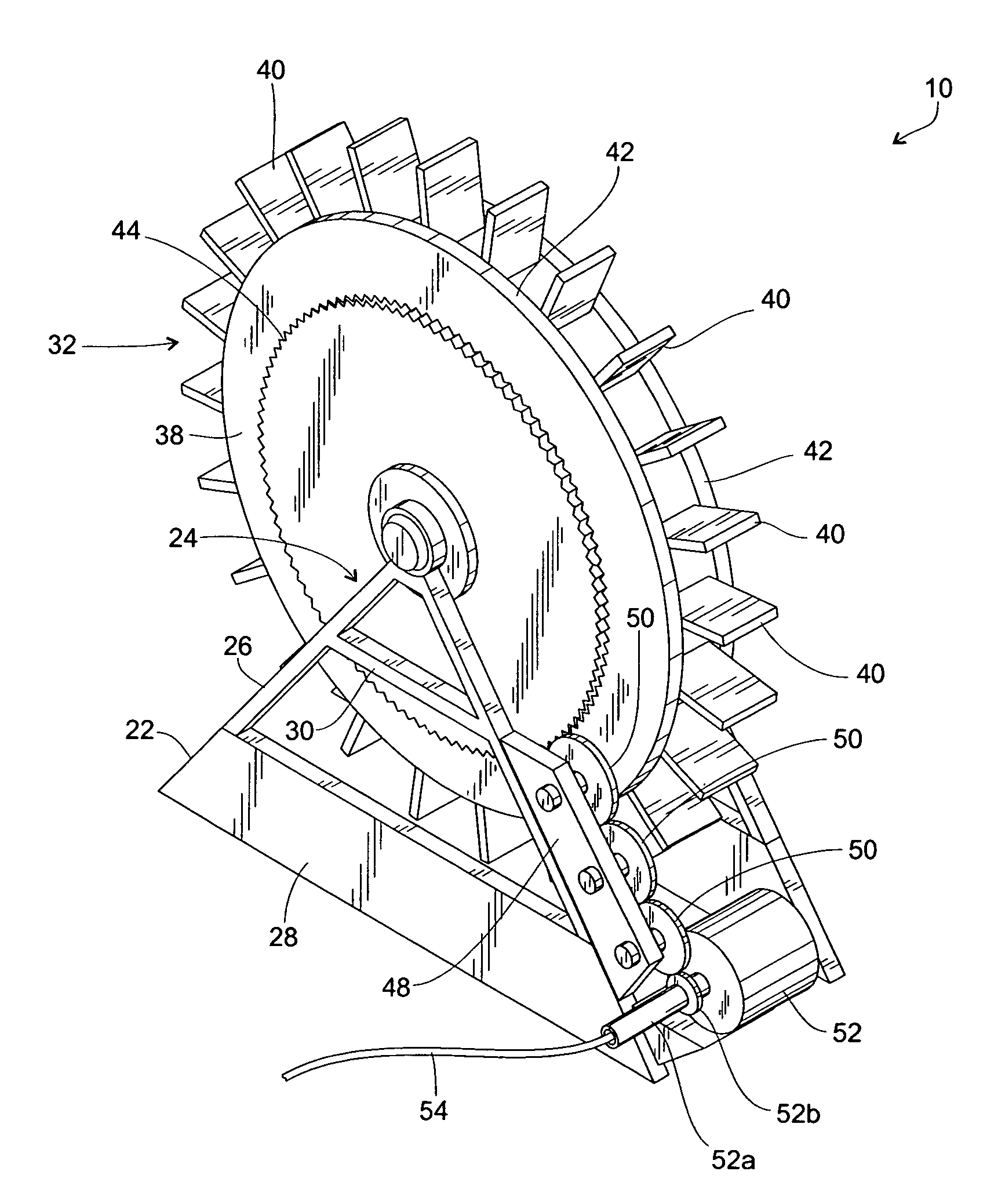
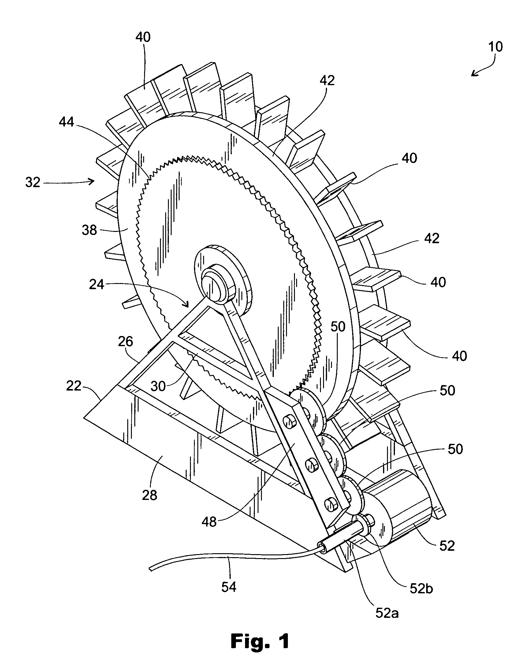
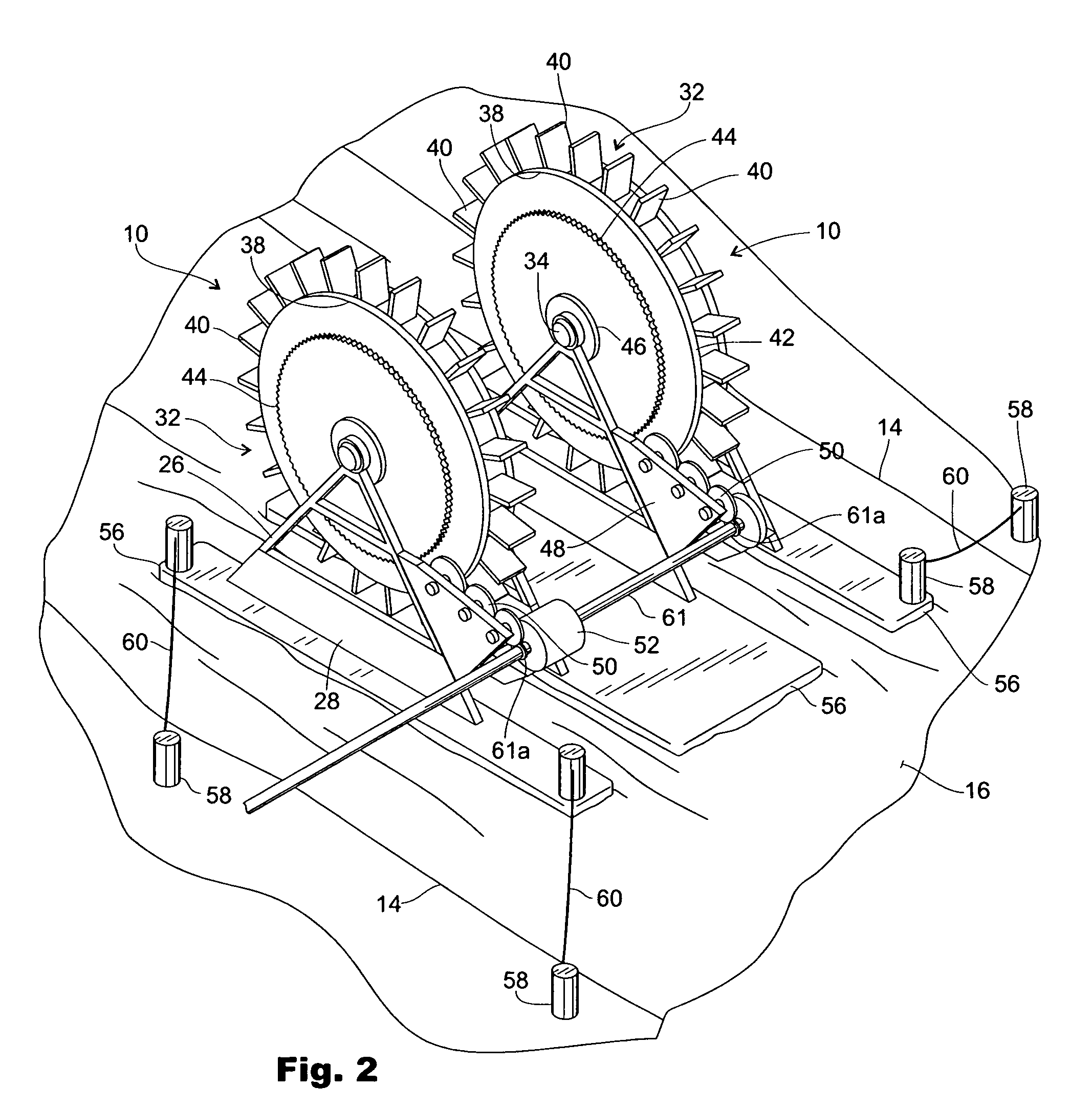
[0026]Illustrated in FIGS. 1-6 is a paddle wheel electric generation device 10 for producing pollution-free electricity at low cost or no cost by utilizing the inherent force of nature as manifested in any appropriate hard running and swift flowing narrow water course such as any swiftly flowing mountain stream especially where there is a descent in the stream that enhances the flow velocity of the stream. Thus, shown in FIGS. 2 and 3 is a representative watercourse 12 such as a narrow, hard-flow stream defined by opposed stream banks 14 and having a stream surface 16 and a streambed or bottom 18.

[0027]As shown in FIGS. 1-3, the paddle wheel generation device 10 is disposed in the stream 12 for harnessing the energy of the flowing stream 12 for the generation of electricity. The device 10 includes a mounting means for securing the device 10 to the streambed, and one preferred embodiment for the mounting means is an A-frame base 20 preferably of concrete. The A-frame base 20 is fixed...


PUM


Abstract

A minimal maintenance paddle wheel electric generation device for producing no cost electricity includes an A-frame base disposed in a fast flowing stream with a paddle wheel mounted between A-frame supports, with the supports resting on the base, and the paddle wheel including radially arranged dip blades with the rotation of the paddle wheel by the swiftly running water turning a drive gear that engages a series of reduction gears that, in turn, actuate a generator for producing electricity. A pair of paddle wheels can be ganged together on several floating members with the floating members tethered by cables to stanchions fixed on opposed banks of the stream. The paddle wheel can also be supported on buoyant inflatable tubes that have curvilinear members attached to the rear ends for directing water into the channel formed between the tubes thereby enhancing water flow and the angular speed of the paddle wheel for increased power generation.

Description

FIELD OF THE INVENTION[0001]The present invention pertains to hydroelectric generation devices, and more particularly pertains to a fixed or floating paddle wheel electric generation device located in narrow, hard flow watercourses.BACKGROUND OF THE INVENTION[0002]With energy needs of society growing each year, efforts to obtain the maximum benefit from conventional and alternative sources has intensified in recent years. Technology and capital is being harnessed and allocated to search for new energy sources that range from deep-water oil drilling off the continental shelves to hydrogen fusion and from windmills to natural gas. Hydroelectric power is also being employed as most notably attested to by the Three River Gorges dam in China. However, hydroelectric power generation doesn't have to be limited to locations astride the major rivers of the world. Numerous geographic locales include swiftly running or hard running streams that if properly utilized could provide the power need...

Claims


Application Information

Patent Timeline
Patent Type & Authority Patents(United States)
IPC IPC(8): F03B13/00F03B13/10
CPCF03B17/063Y02E10/28F05B2240/932Y02E10/30Y02E10/20
Inventor WINIUS, HENRY C.
Owner WINIUS HENRY C
Why Eureka
Try Eureka