Drilling rigs and erection methods
- Summary
- Abstract
- Description
- Claims
- Application Information
AI Technical Summary
Benefits of technology
Problems solved by technology
Method used
Image


Examples
Embodiment Construction
[0059]FIGS. 6A-6D show a rig 10 according to the present invention erected by a method according to the present invention.
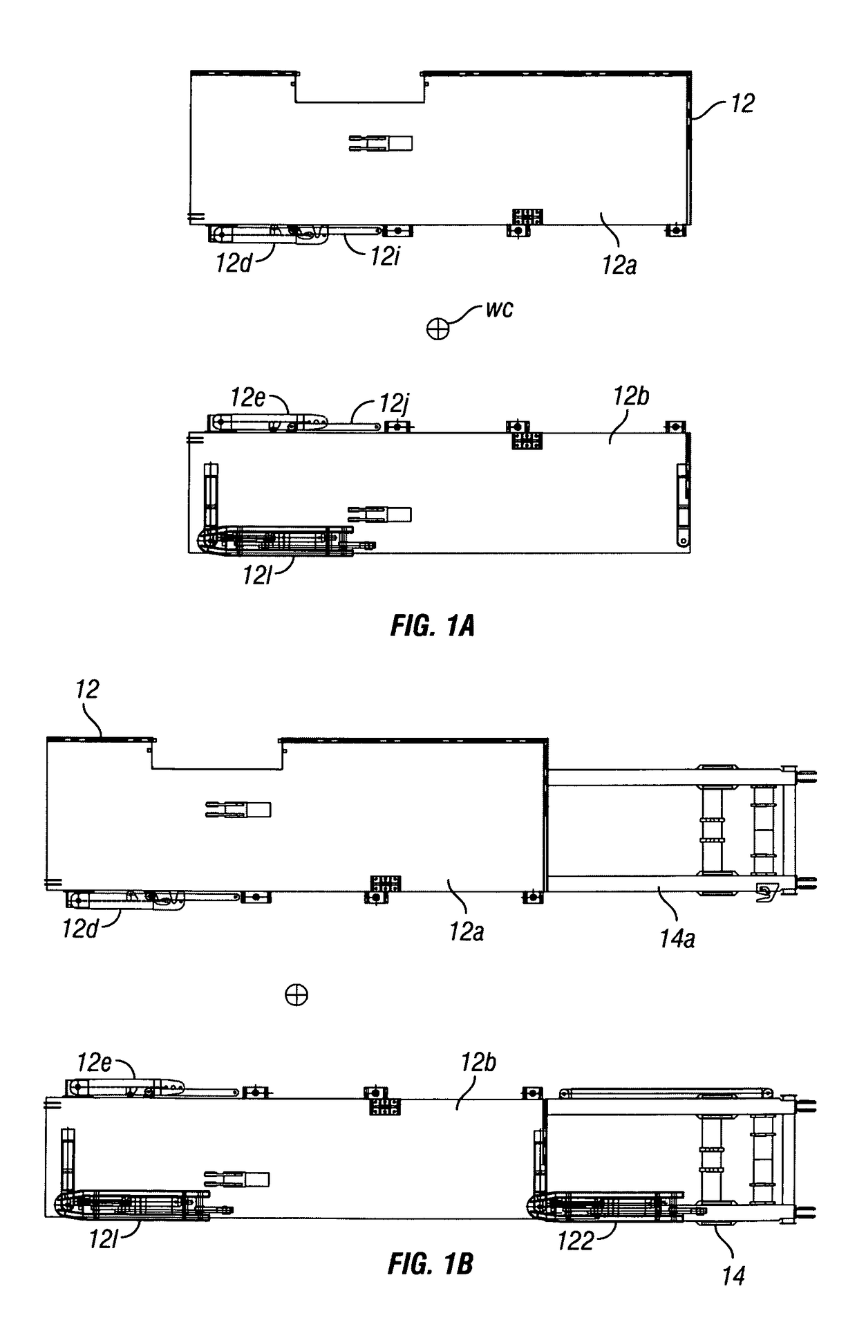
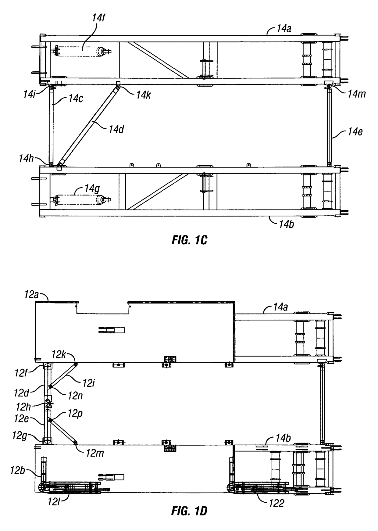
[0060]FIG. 1A shows an upper box 12 of a substructure 20 or the rig 10 according to the present invention. FIG. 1B shows the upper box 12 above a base box 14 of the rig substructure 20. The upper box 12 includes side floor section 12a, side floor section 12b, upper box beam 12c which includes parts 12d and 12e. The parts 12d and 12e pivot, respectively, about pivot connections 12f, 12g and these have ends which are releasably connectable to each other with a pin 12h as shown in FIG. 1D. Braces 12i, 12j are pivotably connected to pivot connections 12k, 12m, respectively and are pivotable to releasably connect to the parts 12d, 12e at points 12n, 12p, respectively, as shown in FIG. 1D. Optionally, the rig 10 has pivotable suspension arms 121, 122 which are useful in securing an item, e.g. a rig structure such as a doghouse DH (see FIG. 6F) to the rig.
[0061]The base...
PUM
 Abstract
Description
Claims
Application Information