Counter-biased valve and actuator assembly

a technology of actuator assembly and valve, applied in the field of mechanical arts, can solve the problems of reducing the responsiveness of the actuator to control the valve, reducing the responsiveness of the actuator to the valve, and typically needing to be biased closed with an extremely high degree, so as to improve the function of the common valve and actuator assembly design, improve the actuation response time, and eliminate, reduce or overcome the effect of force acting

Active Publication Date: 2013-06-25
DAYCO IP HLDG
View PDF62 Cites 17 Cited by
  • Summary
  • Abstract
  • Description
  • Claims
  • Application Information

AI Technical Summary

Benefits of technology

[0011]Another object of the embodiments described herein is to provide a valve and valve actuator assembly, counter-biased by a working fluid (or gas) pressure, for improving the function of a common valve and actuator assembly design, as it is known heretofore.
[0012]Another object is to provide a valve and valve actuator assembly, counter-biased by working fluid (or gas) pressure, that eliminates, reduces, or overcomes a force acting on the face of a valve by communicating a common working pressure of the fluid (or gas) to a substrate with a resultant force vector opposite the valve face.
[0013]Another object is to provide a valve and valve actuator assembly, counter-biased by a working fluid (or gas) pressure, that reduces the need for unnecessarily high spring or force pre-loads to bias the valve closed against the fluid (or gas) working pressure.
[0014]Another object is to provide a valve and valve actuator assembly, counter-biased by a working fluid (or gas) pressure, that improves the actuation response time, measured by the ability of the valve to operate at higher frequencies, by reducing or eliminating the spring or force pre-load to bias the valve.

Problems solved by technology

The main drawback with conventional valve actuator assemblies is that the valve typically needs to be biased closed with an extremely high spring pre-load in order to counter-act or negate the force created by the working pressure of fluid (or gas) against the face of the valve.
Another problem with conventional valve actuator assemblies is that the high spring pre-load requirement reduces the responsiveness of the actuator to control the valve.
Another problem with conventional valve actuator assemblies is that they are typically over-designed to be far more robust than they would otherwise need to be in order to withstand the high spring pressures mentioned heretofore.

Method used


Image

  • Counter-biased valve and actuator assembly
  • Counter-biased valve and actuator assembly
  • Counter-biased valve and actuator assembly

Examples


Embodiment Construction

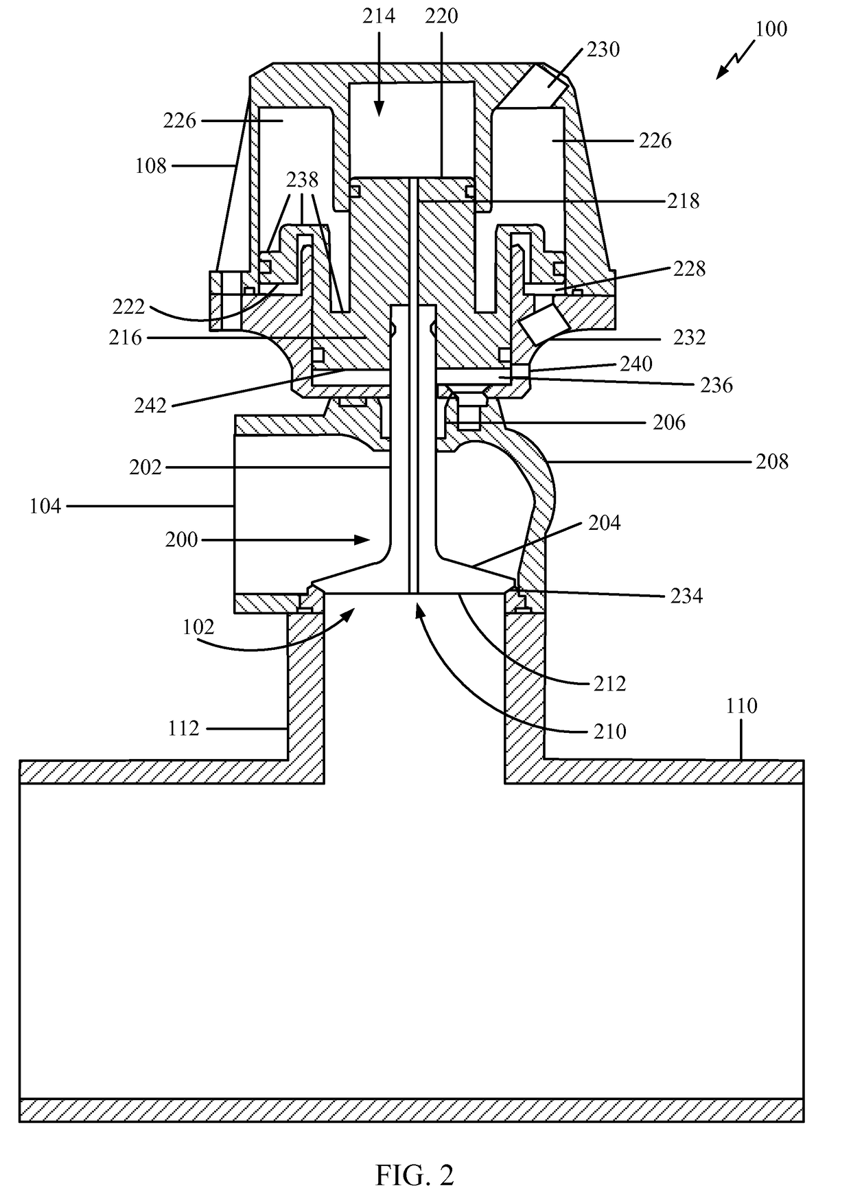
[0023]Valve actuator assemblies are typically used to control the position of a valve in applications to perform flow or pressure regulation through the valve actuator assembly. The embodiments described herein provide for an ability to alter the influence of working pressures acting on a face of a valve in such an assembly. The fluid or gaseous pressure acts on a surface area of the valve face and generally produces a resultant force in a vector normal and opposite to this surface. One of the primary objectives of the embodiments disclosed herein is to reduce, eliminate, or overcome the force of the working pressure on the valve face.

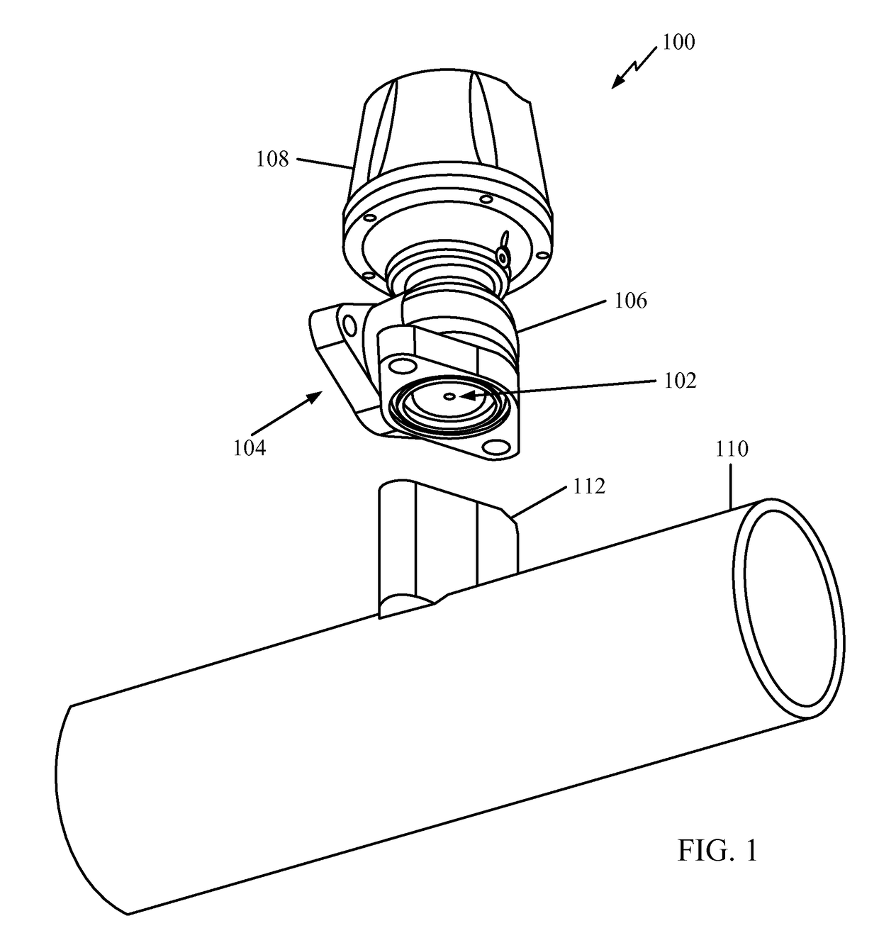
[0024]Turning now to the drawings, FIG. 1 illustrates a valve actuator assembly in accordance with one embodiment, shown in a perspective view. Valve actuator assembly 100 comprises an inlet port 102, an outlet port 104, a valve housing 106, and an actuator housing 108. Other components of valve actuator assembly 100, not visible in FIG. 1, will be des...


PUM


Abstract

A valve actuator assembly, counter-biased by a working fluid (or gas) pressure, is disclosed. The valve actuator assembly comprises a valve and a pneumatic or hydraulic actuator. A port is defined axially through the valve and actuator that communicates a working fluid (or gas) pressure acting on the valve face to a counter-biasing chamber inside an actuator housing. This design eliminates, reduces, or overcomes a force acting on a face of the valve by communicating a common working pressure of the fluid (or gas) to a substrate on the actuator with a resultant force vector opposite the valve face.

Description

BACKGROUND[0001]1. Field of Use[0002]The embodiments described herein relate to the mechanical arts. More specifically, the present invention relates to valve actuator assemblies.[0003]2. Description of the Related Art[0004]It can be appreciated that valve actuator assemblies have been in use for years. These assemblies control the flow of liquids or gasses in a variety of industrial and mechanical settings. Typically, valve actuator assemblies comprises one of three main types of design: those comprising diaphragm actuators, actuator pistons, or electromechanical actuators. These assemblies are typically used in controlling one or more functions of internal combustion engines or in other industrial applications.[0005]The main drawback with conventional valve actuator assemblies is that the valve typically needs to be biased closed with an extremely high spring pre-load in order to counter-act or negate the force created by the working pressure of fluid (or gas) against the face of ...

Claims


Application Information

Patent Timeline
Patent Type & Authority Patents(United States)
IPC IPC(8): F16K31/00
CPCF16K31/1223F16K31/12F16K31/1226Y10T137/0379
Inventor MEDINA, PETER JOHANN
Owner DAYCO IP HLDG
Why Eureka
Try Eureka