Rotatable test element

a test element and rotational technology, applied in the field of analytical test devices, can solve the problems of difficult immobilization of reagents, inability to absorb the matrix, and inability to immobilize the reagen

Active Publication Date: 2013-06-25
ROCHE DIAGNOSTICS OPERATIONS INC
View PDF15 Cites 78 Cited by
  • Summary
  • Abstract
  • Description
  • Claims
  • Application Information

AI Technical Summary

Problems solved by technology

A disadvantage of the optical lab-disks or bio-disks that are based purely on centrifugal and capillary forces is that it is difficult to immobilize reagents and the accuracy of the detection suffers.
A disadvantage of the concepts of the prior art is that a specific control of the reaction and dwelling times of the sample liquid after uptake of the reagents and after they have flowed into the porous, absorbent matrix is not possible especially for specific binding assays such as, e.g., immunoassays.

Method used


Image

  • Rotatable test element
  • Rotatable test element
  • Rotatable test element

Examples


example 1

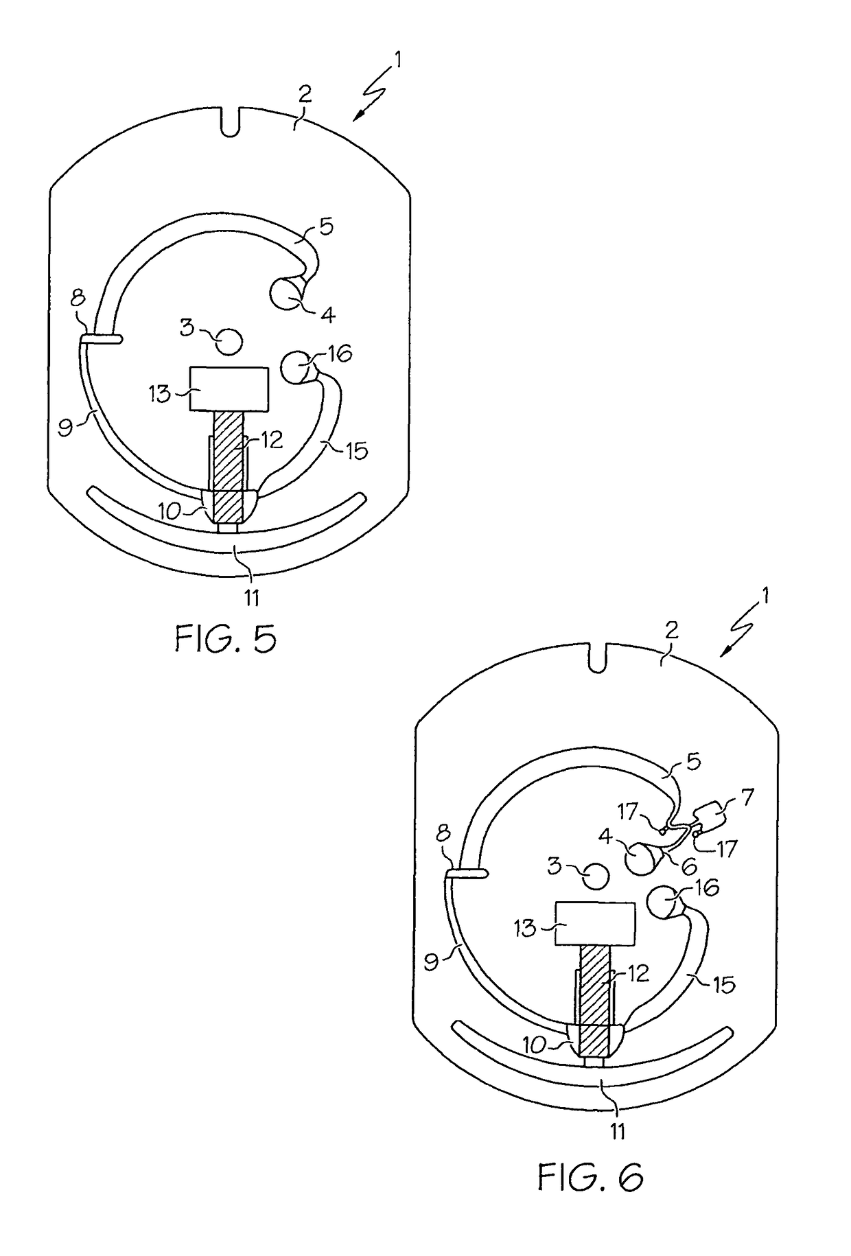
Preparation of a Test Element According to FIG. 6

1.1 Preparation of the Substrate (2)

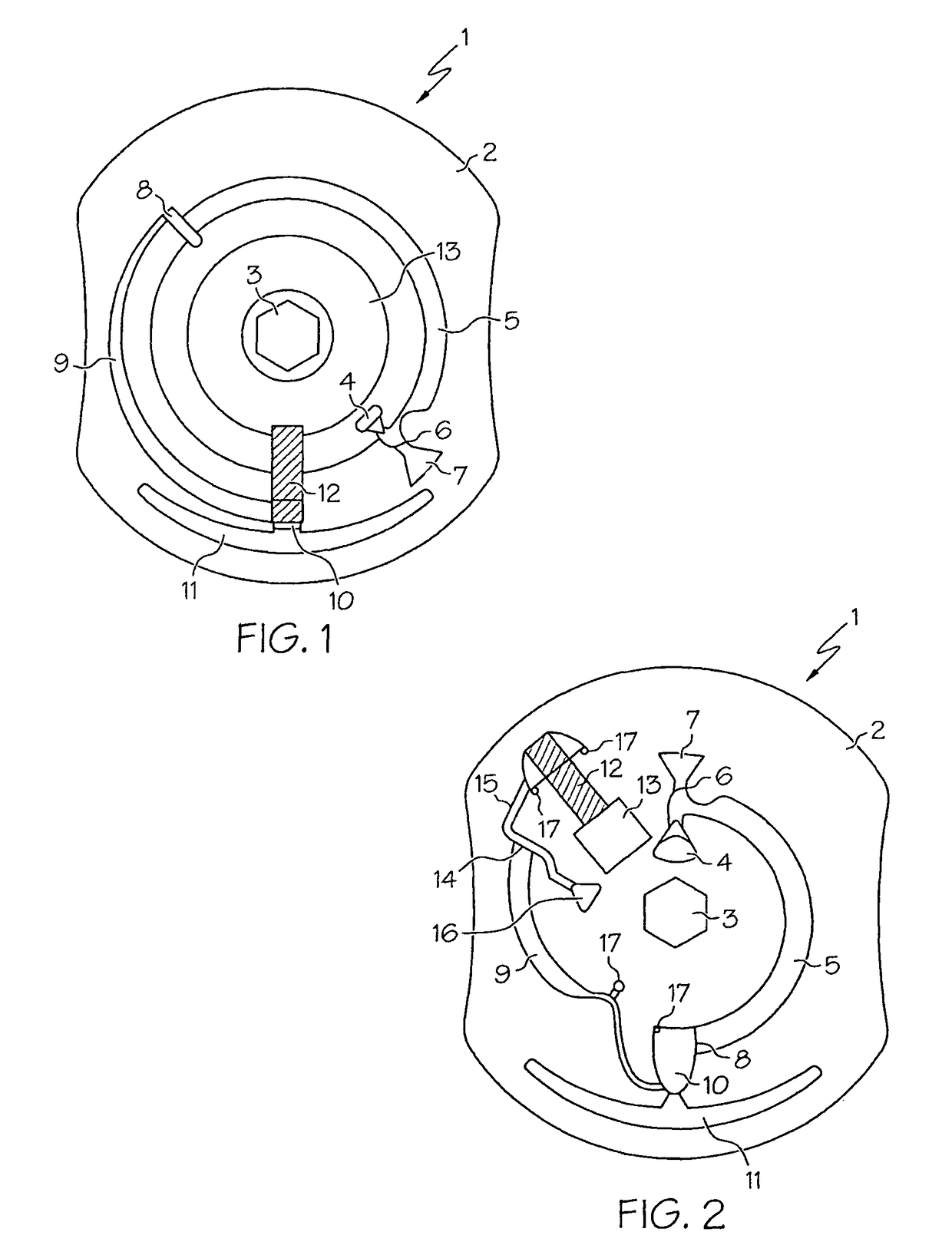
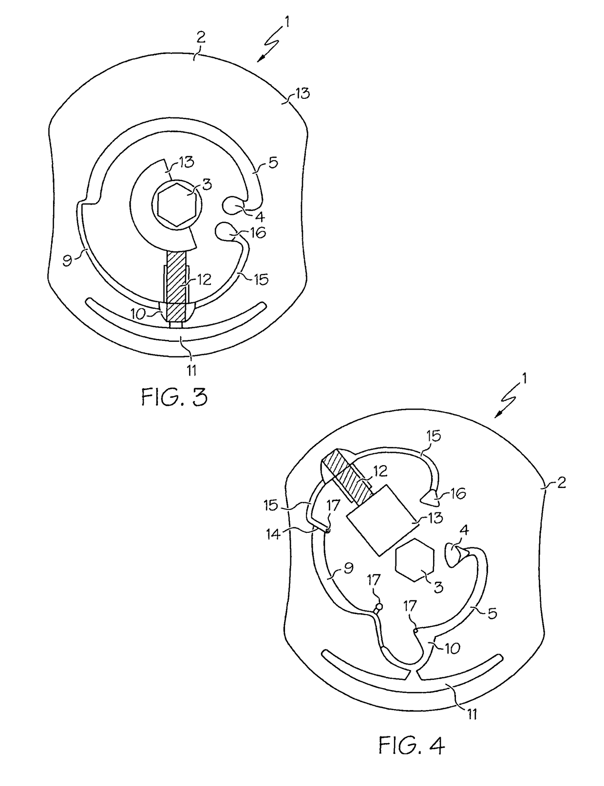
[0098]A substrate (2) according to FIG. 6 (dimensions about 60×80 mm2) is manufactured by means of injection molding from polycarbonate (PC) (alternatively polystyrene (PS), ABS plastic or poylmethylmethacrylate (PMMA) can also be used as the material). The individual channels and zones (fluidic structures) have the following dimensions (depth of the structures (d) and optionally their volumes (V); the numerals refer to FIG. 6 and the structures shown therein):[0099]capillary between 4 and 5: d=500 μm[0100]No. 7: d=700 μm[0101]No. 5: d=150 μm; V=26.5 mm3 [0102]No. 8: d=500 μm[0103]No. 9: d=110 μm[0104]No. 10: d=550 μm[0105]No. 11: d=130 μm; V=15 mm3 [0106]No. 15: d=150 μm; V=11.4 mm3

[0107]A transition from less deep to deeper structures is usually only possible for liquids in the fluidic structures when force (e.g., centrifugal force) acts from outside. Such transitions act as geometric (non-closin...

example 2

Detection of Troponin T with the Aid of the Test Element from Example 1

[0120]27 μl whole blood to which different amounts of recombinant troponin T were admixed were applied to the test element according to example 1. The test element is subsequently treated further according to the process stated in table 1 and finally the fluorescence signals for different concentrations are measured.

[0121]

TABLE 1Measuring processRotation atrevolutionsTimeDurationper(min:sec)(min:sec)minuteAction00:0001:000apply 27 μl sample; dissolve the reagents01:0002:005000erythrocyte separation and incubation03:0001:00800chromatography (signal generation)04:0000:100apply 12 μl washing buffer1)04:1002:00800washing buffer transport and chromatography06:1000:100apply 12 μl washing buffer1)06:2002:00800washing buffer transport and chromatography08:2000:100apply 12 μl washing buffer1)08:3002:00800washing buffer transport and chromatography10:300Measure1)100 mM Hepes, pH 8.0; 150 mM NaCl; 0.095% sodium azide.

[0122]...


PUM

PropertyMeasurementUnit
widthaaaaaaaaaa
distanceaaaaaaaaaa
lengthaaaaaaaaaa

Abstract

A test element and method for detecting an analyte with the aid thereof is provided. The test element is essentially disk-shaped and flat, and can be rotated about a preferably central axis which is perpendicular to the plane of the disk-shaped test element. The test element has a sample application opening for applying a liquid sample, a capillary-active zone, in particular a porous, absorbent matrix, having a first end that is remote from the axis and a second end that is near to the axis, and a sample channel which extends from an area near to the axis to the first end of the capillary-active zone that is remote from the axis.

Description

BACKGROUND OF THE INVENTION[0001]The present invention relates generally to analytical test devices and, more particularly, to a rotatable test element and method for detecting an analyte with the aid of the test element.[0002]In principle the systems for analysing liquid sample materials or sample materials which can be converted into a liquid form can be divided into two classes. On the one hand, there are analytical systems which operate exclusively with so-called wet reagents and, on the other hand, there are systems which use so-called dry reagents. In particular in medical diagnostics and also in environmental and process analytics the former systems are primarily used in permanently equipped laboratories whereas the latter systems are used mainly for “on-site” analyses.[0003]Analytical systems using dry reagents are offered in the field of medical diagnostics especially in the form of so-called test carriers, e.g., test strips. Prominent examples of this are test strips for d...

Claims


Application Information

Patent Timeline
Patent Type & Authority Patents(United States)
IPC IPC(8): G01N33/53G01N31/22G01N21/00G01N21/75G01N9/30
CPCB01L3/5023B01L3/502738B01L3/502753B01L3/50273Y10T436/110833B01L2200/0605B01L2300/0663B01L2300/0681B01L2300/069B01L2300/0806B01L2300/0861B01L2400/0406B01L2400/0409B01L2400/0688B01L2400/082Y10T436/111666
Inventor BOEHM, CHRISTOPHORANTH, NORBERTSPINKE, JUERGEN
Owner ROCHE DIAGNOSTICS OPERATIONS INC
Why Eureka
Try Eureka