Magnetic head suspension having a load beam part with bending lines

a technology of magnetic head suspension and load beam, which is applied in the direction of maintaining head carrier alignment, recording information storage, instruments, etc., can solve the problems of reducing the bending process affecting the bending accuracy of the load beam part, and the inability to disclose the configuration of documents, etc., to reduce the displacement as much as possible of the magnetic head slider, and the effect of easy manufacturing

Active Publication Date: 2013-06-25
SANCALL CORP
View PDF8 Cites 1 Cited by
  • Summary
  • Abstract
  • Description
  • Claims
  • Application Information

AI Technical Summary

Benefits of technology

[0014]The present invention has been made in view of the above conventional art, and it is an object thereof to provide a magnetic head suspension with a load beam part including a plate-like main body portion that faces a disk surface and paired flange portions that are bent from both side edges of the main body portion in a suspension width direction so as to extend toward a direction opposite from the disk surface, the magnetic head suspension capable of reducing as much as possible displacement of a magnetic head slider due to vibrations of a first torsion mode and a first bending mode while being readily manufactured.

Problems solved by technology

Since the bending directions of the load beam part at the proximal-side bending line and the distal-side bending line are different from each other as explained above, there is a problem that a bending process of the load beam part is made difficult.
In a case where the load beam part with such flange portions is bent in such a convex manner as to project in the direction away from the disk surface at the bending line along the suspension width direction, there is also a problem that the flange portions are likely to be deformed.
Further, the prior art documents do not disclose a configuration for simultaneously minimizing both a displacement amount of the magnetic head slider due to the vibration of the first torsion mode and a displacement amount of the magnetic head slider due to the vibration of the first bending mode.

Method used


Image

  • Magnetic head suspension having a load beam part with bending lines
  • Magnetic head suspension having a load beam part with bending lines
  • Magnetic head suspension having a load beam part with bending lines

Examples


Embodiment Construction

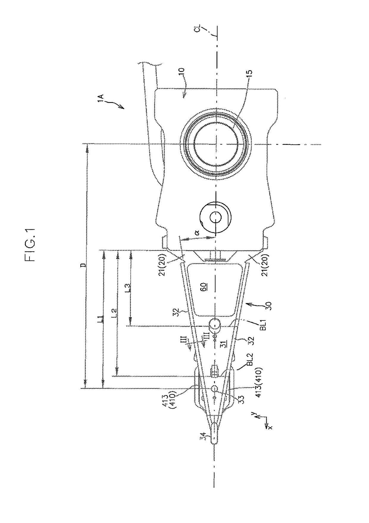
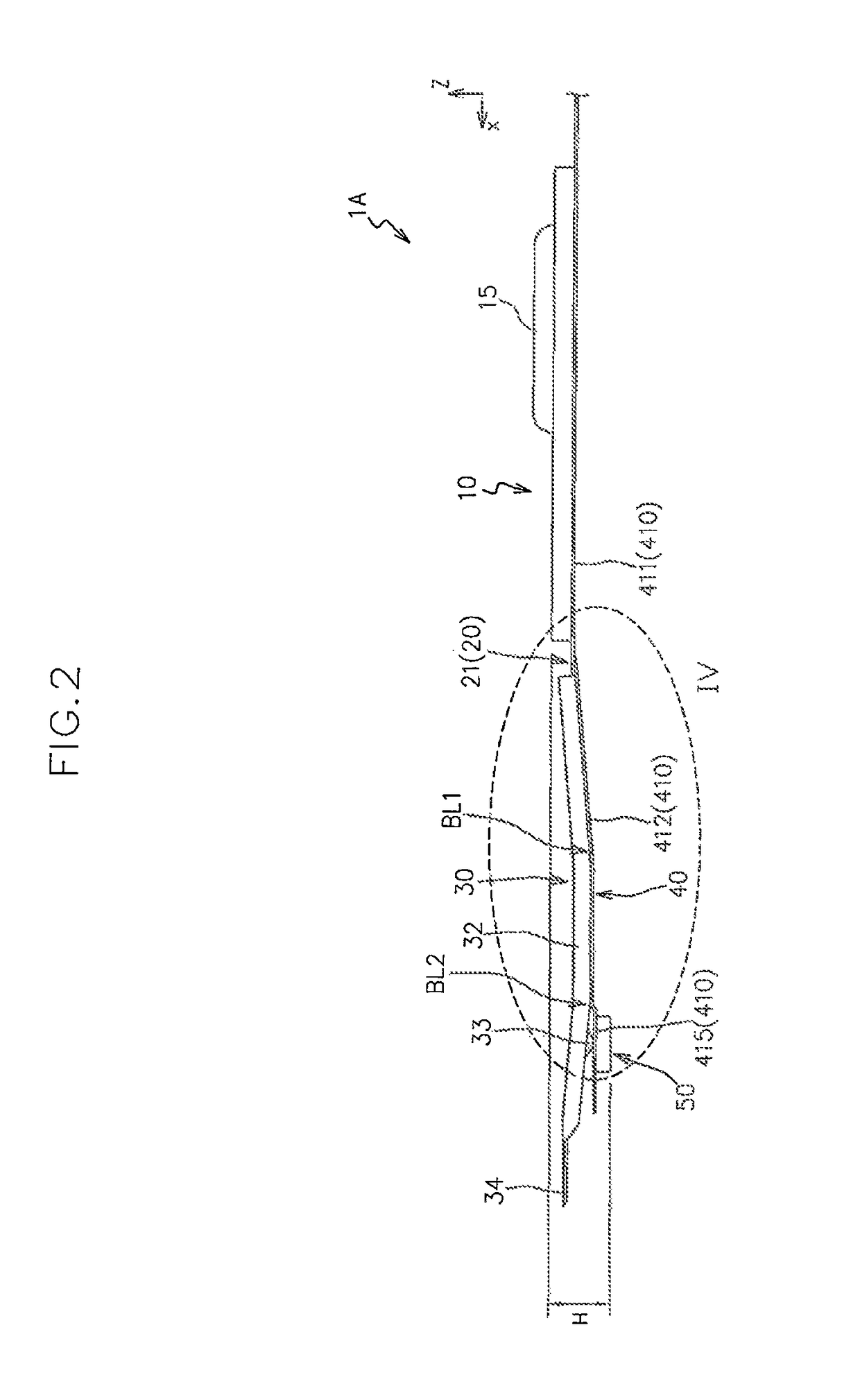
[0049]Hereinafter, a preferred embodiment of a magnetic head suspension according to the present invention will be described, with reference to the attached drawings.

[0050]FIGS. 1 and 2 are a top view (a plan view as viewed from a side opposite from a disk surface) and a side view of a magnetic head suspension 1A according to the present embodiment, respectively.

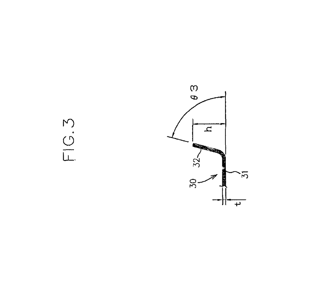
[0051]As shown in FIGS. 1 and 2, the magnetic head suspension 1A includes a supporting part 10 that is swung in a seek direction parallel to the disk surface directly or indirectly by an actuator (no shown) such as a voice coil motor, a load bending part 20 that is connected to the supporting part 10 so as to generate a load for pressing a magnetic head slider 50 toward the disk surface, a load beam part 30 that is supported through the load bending part 20 by the supporting part 10 and transmits the load to the magnetic head slider 50, and a flexure part 40 that is supported by the load beam part 30 and the supporting part ...


PUM

PropertyMeasurementUnit
bending anglesaaaaaaaaaa
thicknessaaaaaaaaaa
thicknessaaaaaaaaaa

Abstract

A load beam part, which includes a plate-like main body portion facing a disk surface and paired flange portions bent from both side edges of the main body portion in a suspension width direction so as to extend toward a direction opposite from the disk surface, is bent at first and second bending lines in such a convex manner as to project in the direction toward the disk surface, the first bending line being positioned between the proximal end portion of the load beam part and the dimple in the suspension longitudinal direction and extending along the suspension width direction, the second bending line being positioned between the first bending line and the dimple in the suspension longitudinal direction and extending along the suspension width direction.

Description

BACKGROUND OF THE INVENTION[0001]1. Field of the Invention[0002]The present invention relates to a magnetic head suspension for supporting a magnetic head slider that reads and / or writes data from and to a recording medium such as a hard disk drive.[0003]2. Related Art[0004]A magnetic head suspension that supports a magnetic head slider is required to accurately position the magnetic head slide to a center of a target track.[0005]More specifically, the magnetic head suspension is directly or indirectly connected at a proximal side to an actuator such as a voice coil motor, and positions the magnetic head slider, which it supports at a distal side, to the center of the target track by being swung around a swing center by the actuator.[0006]By the way, if the magnetic head suspension resonates at the time when being swung around the swing center, the magnetic head slider is largely displaced from the target track. In particular, out of the various vibration modes possibly generated in...

Claims


Application Information

Patent Timeline
Patent Type & Authority Patents(United States)
IPC IPC(8): G11B5/60
CPCG11B5/4833
Inventor FUJIMOTO, YASUO
Owner SANCALL CORP
Why Eureka
Try Eureka