Radio-controlled helicopter

a radio-controlled helicopter and helicopter technology, applied in the field of radio-controlled helicopters, can solve the problems of reducing the weight of the helicopter, affecting the operation of the tail beam, and the structure of the above-mentioned helicopter in its entirety, so as to reduce the cantilever mass as much as possible, and minimise the damage resulting from the crash

Inactive Publication Date: 2014-05-08
SAB HELI DIV
View PDF1 Cites 1 Cited by
  • Summary
  • Abstract
  • Description
  • Claims
  • Application Information

AI Technical Summary

Benefits of technology

[0014]Another aim is to provide a radio-controlled helicopter the tail beam of which allows a better distribution of the weights compared with the prior art solutions thereby reducing as much as possible the cantilever masses.
[0015]A further aim is to define a connecting system between bean and main body designed to minimise the damage resulting from the crash.
[0016]Yet another aim is to provide a radio-controlled helicopter the assembly and maintenance of which is simpler compared with prior art solutions.
[0018]More specifically, the tail beam is made from printed composite material tubular in shape with a variable cross-section. The tail beam is then connected to the main body by a system normally known as “V” joint which with the use of correctly designed connecting devices determines a system for joining the tail beam to the main body of a collapsible type so as to achieve the aim of reducing damage in the case of a heavy crash.

Problems solved by technology

The above-mentioned structure is relatively not very rigid, especially at the coupling of the tail beam to the main body.
To overcome this lack of rigidity of prior art systems supplementary stiffening members are often used such as, for example, tie rods and the like which, however, at the same time can weigh down and complicate the structure of the helicopter in its entirety and the functionality of the tail beam in particular.
Moreover, the interlocking connection system described above does not help to reduce the damage to the main body of the helicopter since in the event of crashing the connection point is stressed enormously due to the high forces in play caused by the impact, thereby irreparably damaging the main body.
The system described is however complex.
Even the maintenance is consequently complex.
For example, it is easy to damage one of the two plates following a crash of the model, with the consequent need to dismantle the majority of the helicopter to replace the damaged part.

Method used


Image

  • Radio-controlled helicopter
  • Radio-controlled helicopter
  • Radio-controlled helicopter

Examples


Embodiment Construction

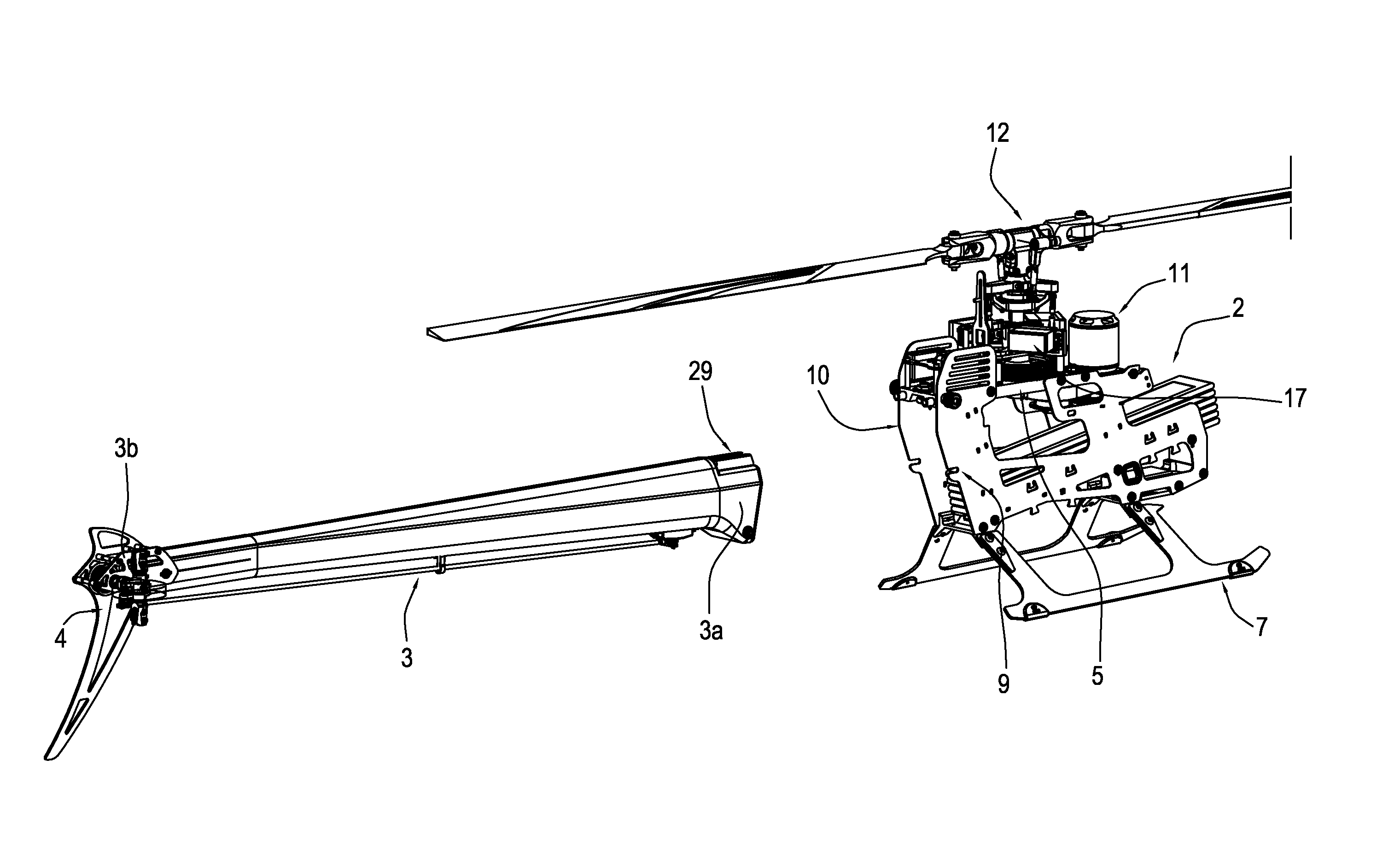
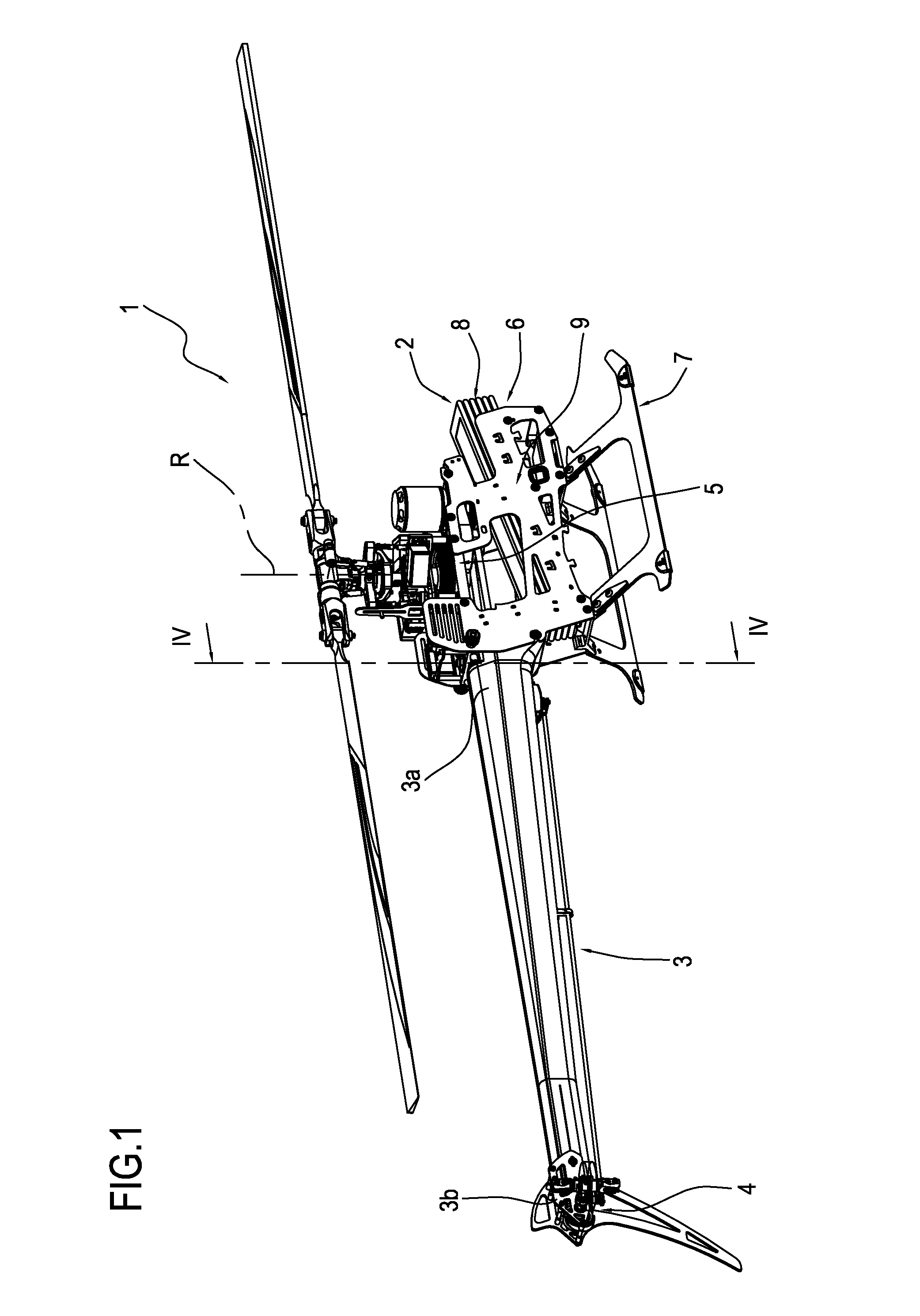
[0029]With reference to the accompanying drawings, with particular reference to the FIGS. 1 to 5, the numeral 1 denotes a radio-controlled helicopter according to this invention.

[0030]The helicopter 1 is described below solely for he parts necessary or the understanding of this invention.

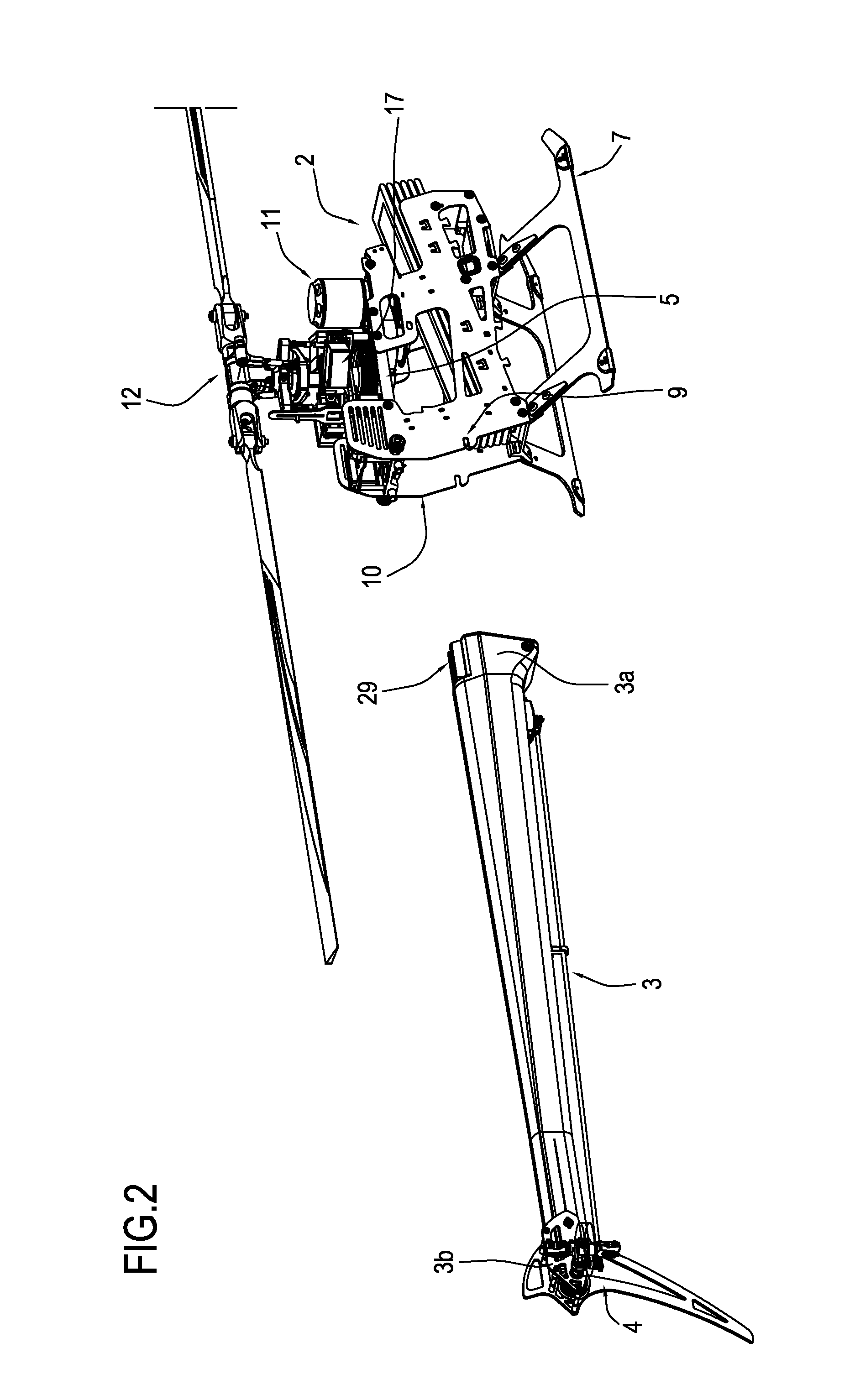
[0031]The helicopter 1 comprises a main body 2 and a tail beam 3 connected to and supported by the main body 2.

[0032]The beam 3 can be removed from the main body 2, as described in more detail below.

[0033]More specifically, the beam 3 has a first end 3a connected, so close, to the main body 2 and a second end 3b, away from the main body 2.

[0034]The tail beam 3 is made from composite materials of a substantially know type and, advantageously, has a tapered tubular profile with the cross-section at the first end 3a greater than the cross-section at the second end 3b.

[0035]The tail beam 3 is, in other words, defined by a tapered tubular member with the cross-section at the first end 3a greater than th...


PUM


Abstract

Described is a radio-controlled helicopter comprising a main body, a tail beam, connecting means operating between the main body and the tail beam for connecting the tail beam to the main body; the tail beam has a first end close to the main body and a second end away from the main body and it is defined by a tapered tubular member with a cross-section at the first end greater than the cross-section at the second end; the connecting means comprise an engagement member integral with the tail beam in the first end and a seat for the engagement member made in the main body, and fixing means operating between the engagement member and the main body at the seat.

Description

TECHNICAL FIELD[0001]This invention relates to a radio-controlled helicopter and in particular to a radio-controlled helicopter comprising a main or central body and a tail beam connected to the main body and supporting a group of rear blades.BACKGROUND ART[0002]The prior art radio-controlled helicopters comprise a load-bearing structure defined by a main body to which a tail beam is connected.[0003]At present, a prior art tail beam for radio-controlled helicopters is made from a tubular member, with a constant cross-section, generally circular in shape, normally extruded from material such as aluminium. The tubular member is then connected to the main body of the helicopter by a pair of transversal members which interface with the tubular member, forming a fitting between between tubular member and main body.[0004]The above-mentioned structure is relatively not very rigid, especially at the coupling of the tail beam to the main body.[0005]To overcome this lack of rigidity of prior ...

Claims


Application Information

Patent Timeline
Patent Type & Authority Applications(United States)
IPC IPC(8): B64C27/04
CPCB64C27/04A63H27/001A63H27/12
Inventor BERNABEI, ENRICO MARIABAIARDI, STEFANO
Owner SAB HELI DIV
Why Eureka
Try Eureka