Method for defining a laser tool path

a laser tool and path technology, applied in the field of laser machines, can solve the problems of generating defects at the boundary of adjacent patches, not systematically obtaining good, and still appearing defects in certain 3d geometries, so as to reduce the effect of surface quality improvemen

Active Publication Date: 2019-01-03
GF MACHINING SOLUTIONS AG
View PDF5 Cites 2 Cited by
  • Summary
  • Abstract
  • Description
  • Claims
  • Application Information

AI Technical Summary

Benefits of technology

[0021]An aspect of the invention is, in particular, to mitigate all or some of the drawbacks of the prior art. More specifically, an objective of the invention is to reduce as much as possible the duration of the machining work, while obtaining improved surface quality compared to the prior art.

Problems solved by technology

In effect, the traditional ablation method often generates defects at the boundary of the adjacent patches, in the form of boundary lines that are visible at the edges of the patches.
The document WO 0 074 891 also proposes a method for reducing these defects, but without systematically obtaining good results.
This method generally gives excellent results but defects can nevertheless still appear in certain 3D geometries.

Method used


Image

  • Method for defining a laser tool path
  • Method for defining a laser tool path
  • Method for defining a laser tool path

Examples


Embodiment Construction

[0039]Different embodiments according to the invention are described in relation to figures FIG. 1 to FIG. 15.

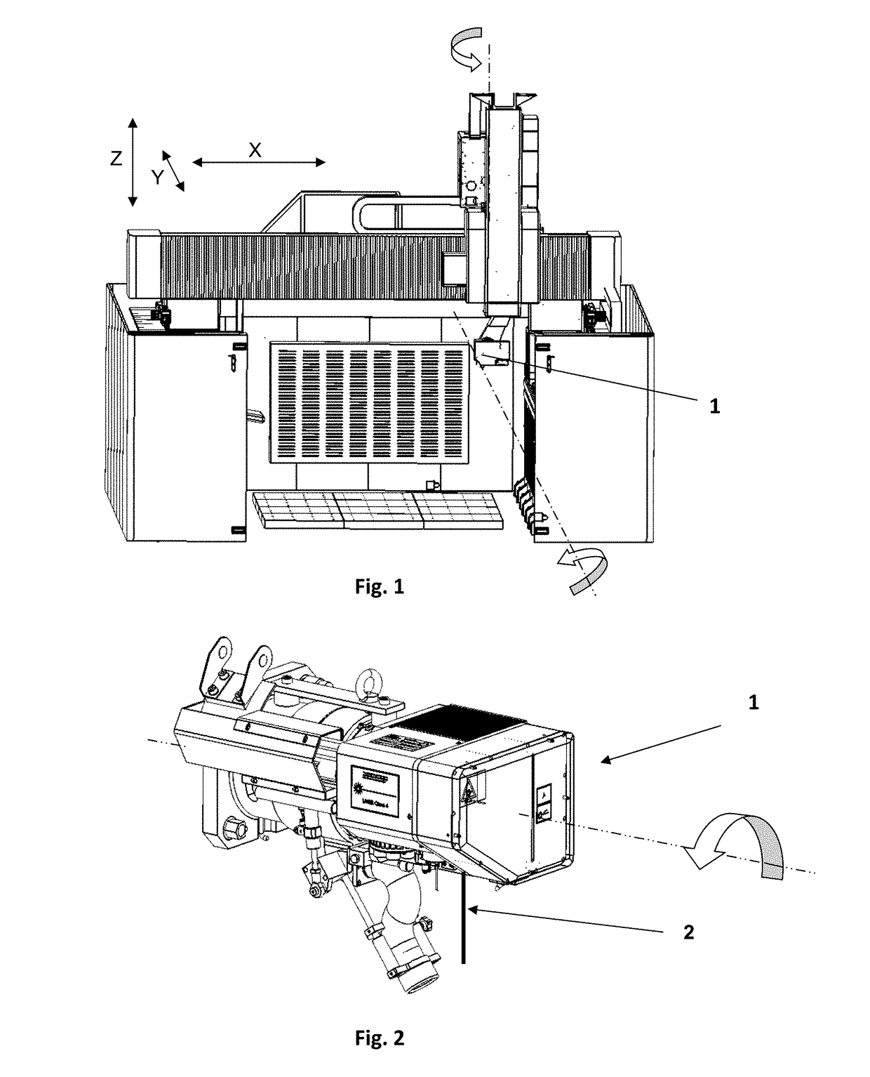
[0040]In order to compute a machining path, a method according to the invention for defining a sequence of relative positionings of a laser head (1) in relation to a part consists of a succession of steps schematically illustrated in FIG. 8.

[0041]In a step 100 of definition of layers, N machining layers 12 are computed in the usual way from 3D modelling data of the part and texturing data.

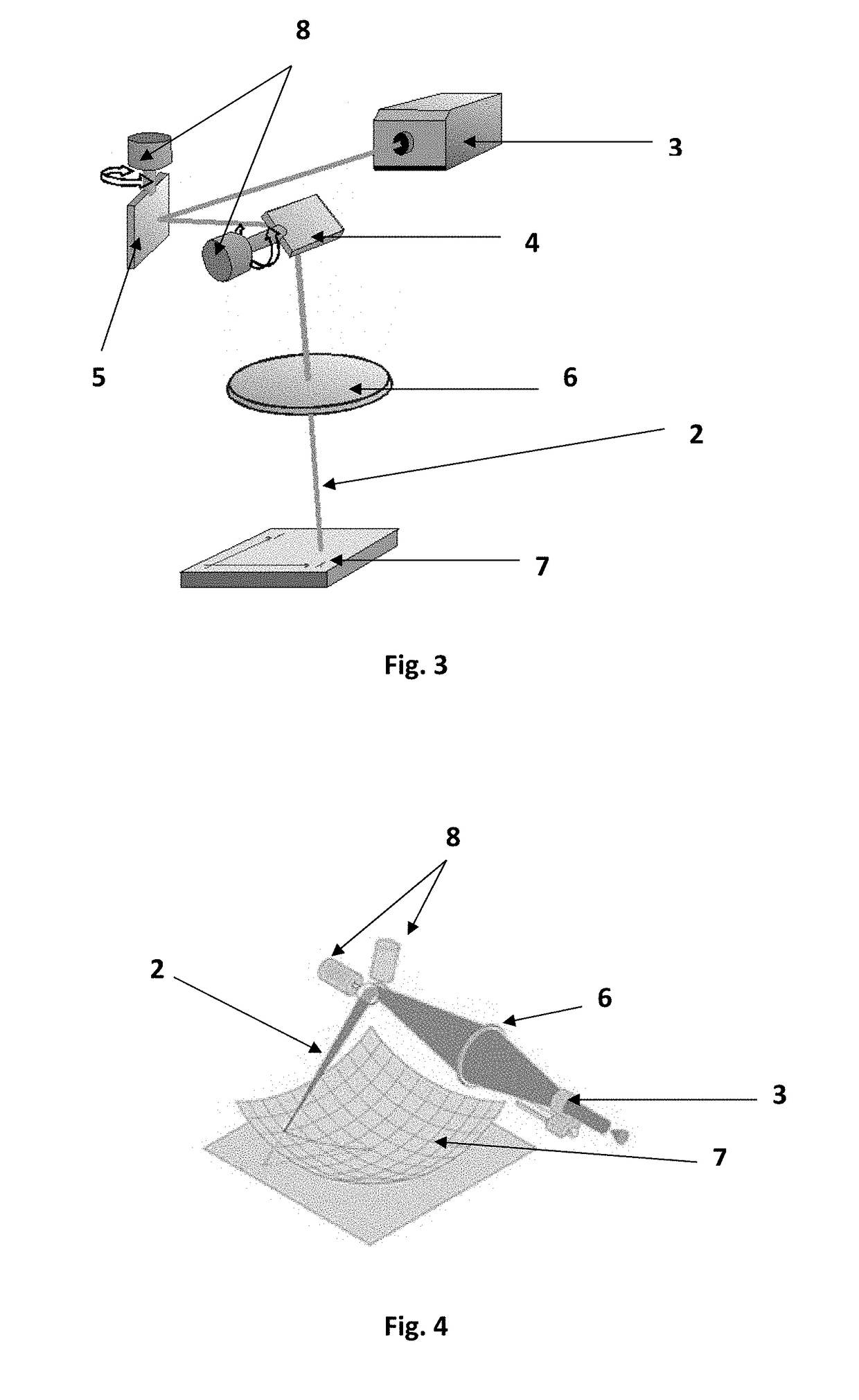
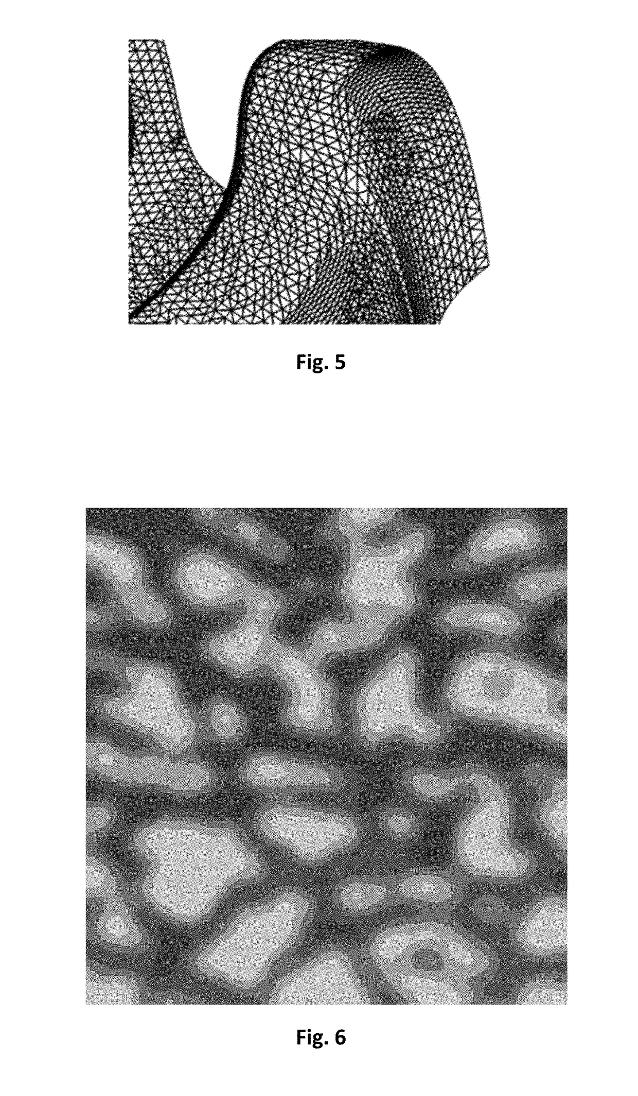
[0042]In a step 200 of definition of closed patches, there are computed, for each machining layer 12, based on elements of the 3D meshing of the part, closed patches 15 each intended to be machined from a single position of the laser head 1, and whose boundary is not affected by the laser ray 2. These closed patches 15 correspond to the patches defined in the document EP 3 047 932.

[0043]FIG. 9 illustrates a part of a machining layer 12 out of the N machining layers. The triangles represent ...


PUM

PropertyMeasurementUnit
focal lengthsaaaaaaaaaa
focal lengthaaaaaaaaaa

Abstract

The present invention relates to a method for defining a sequence of relative positionings of a laser head 1 in relation to a part for the machining of a texture etched on the two-dimensional or three-dimensional surface 7 of the part modelled by a 3D meshing, comprising:
    • a step 100 of definition of N machining layers intended to be performed in succession,
    • a step 200 of definition, for each machining layer, of patches intended to be each machined from a single position of the laser head 1, comprising closed patches 15, the boundary of which is not affected by the laser ray 2,
    • a step 300 of validation of the closed patches 15, successively from the machining layer 1 to the machining layer N.
Open patches whose boundary is affected by the laser ray 2 being defined for any areas which could not be machined from validated closed patches 15. Optionally, the method also comprises a step 400 of merging of the validated closed patches 15 into groups 50 of patches.

Description

CROSS-REFERENCE TO RELATED APPLICATIONS[0001]This application claims the benefit and priority of European Patent Application No. 171785975 filed Jun. 29, 2017. The entire disclosure of the above application is incorporated herein by reference.BACKGROUND OF THE INVENTIONField of the Invention[0002]The invention relates to the field of laser machines, and in particular the definition of efficient machining paths. The invention more particularly targets a method for defining a sequence of relative positionings of a laser head in relation to a part for the machining of parts by laser texturing, as defined by the preamble of claim 1.Discussion[0003]The machines for machining parts by laser texturing are known generally. The patent application EP 2 301 706 describes an example of such a machine.[0004]FIG. 1 schematically represents an example of construction of a laser texturing machine. The head 1 of the machine and the part are positioned in relation to one another according to 5 mechan...

Claims


Application Information

Patent Timeline
Patent Type & Authority Applications(United States)
IPC IPC(8): B23K26/08B23K26/064
CPCB23K26/0869B23K26/064B23K26/0823B23K26/0884B23K26/082B23K26/355B23K26/361B23K26/362
Inventor CONSEIL, DAVIDLAPORTE, CHARLES ERIC
Owner GF MACHINING SOLUTIONS AG
Why Eureka
Try Eureka