Handle for a semi-automatic firearm

a semi-automatic firearm and handle technology, applied in the field of handle for semi-automatic firearms, can solve the problems of operator's skin burning or possibly pinching the operator' many safety and accuracy issues of the belt loop, and the operator's sleeve or skin burning or possibly pinching the operator's skin, etc., to achieve stable firing form and grip, less cost of manufacture, and little to no loss of accuracy

Inactive Publication Date: 2013-07-02
SLIDE FIRE SOLUTIONS
View PDF32 Cites 38 Cited by
  • Summary
  • Abstract
  • Description
  • Claims
  • Application Information

AI Technical Summary

Benefits of technology

[0011]According to another aspect of the invention, a semi-automatic firearm is provided. The firearm includes a trigger. A handle is provided. The handle includes grip portion, and the grip portion defines a channel. A block is configured for rigid attachment to the firearm. The block is slidably disposed in the channel for guiding longitudinal movement of the firearm relative to the handle. A trigger guard extends from the grip portion for disposition on one side of the trigger of the firearm. The trigger guard extends longitudinally forward for stabilizing a stationary object, such as a shooter's finger, to intermittently collide with the trigger in response to the firearm being moved longitudinally forward by a predetermined distance relative to the handle.
[0012]The subject invention allows the operator to maintain a stable firing form and grip while rapidly re-firing their semi-automatic firearm with little to no loss in accuracy. In contradistinction to some of the devices of the prior art, the operator must manually push the firearm forward relative to the handle to activate the trigger following each recoil event. Therefore, each discharge event of the firearm is under the uninterrupted control of the operator's human muscle power. The present invention achieves these results without any springs, cylinders, pistons, strings, wheels, or other external mechanical devices to absorb or manipulate the recoil of the firearm. The absence of external mechanical devices means that the present invention is less expensive to manufacture and less likely to fail than the prior art devices. The invention enables generally universal functionality without respect to ammunition type. Additionally, the invention fosters a unique rhythmic shooting style that will add enjoyment and excitement to the sport of shooting firearms. The subject invention can be designed for use with a wide range of semi-automatic firearm types, including both rifle and pistol styles.

Problems solved by technology

Although able to achieve a high rate of firing, the belt loop has many safety and accuracy issues.
This could lead to skin burns or possibly pinch the operator's sleeve or skin in the action.
Another issue with the belt loop method arises because the operator cannot have a firm grip on the stock or the pistol grip of the firearm.
Because of this unnatural and unbalanced firing grip, the firearm is very difficult to aim and control during the belt loop method.
However, the same safety and accuracy issues of the belt loop method apply to these devices because the firearm cannot be held securely with the trigger hand or the stock of the firearm.
One significant drawback of the Akins '918 construction is that automatic mechanisms of this type have been scrutinized for violating federal firearms laws.
Another drawback is that different spring sizes (i.e., different resistance characteristics) may be required from one unit to the next depending on the type of ammunition used so that the springs do not overpower the recoil energy.
This of course introduces inventory complexities.

Method used


Image

  • Handle for a semi-automatic firearm
  • Handle for a semi-automatic firearm
  • Handle for a semi-automatic firearm

Examples


Embodiment Construction

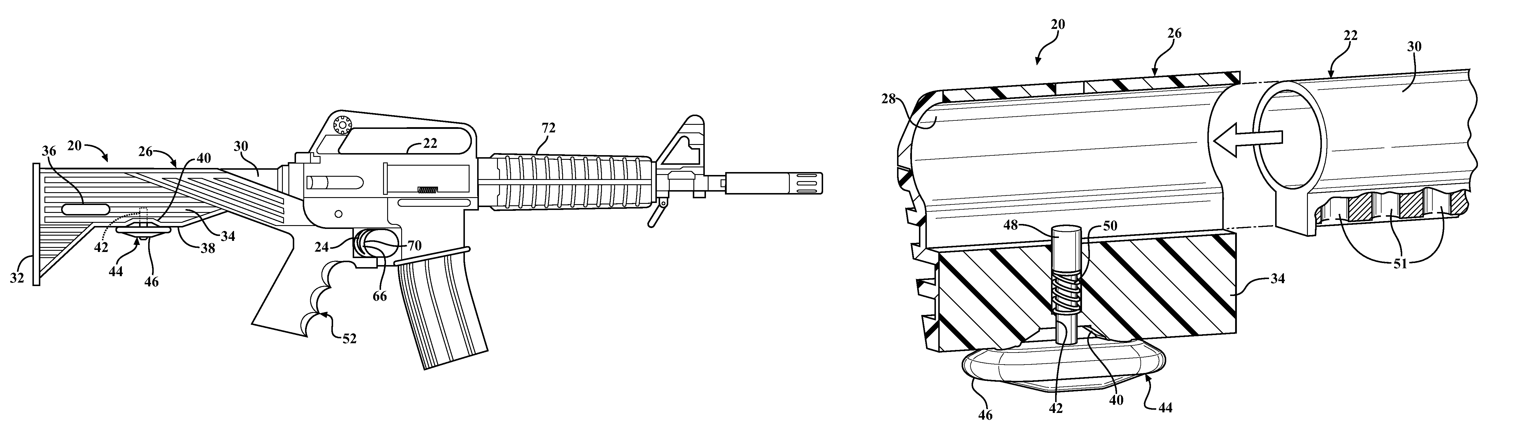
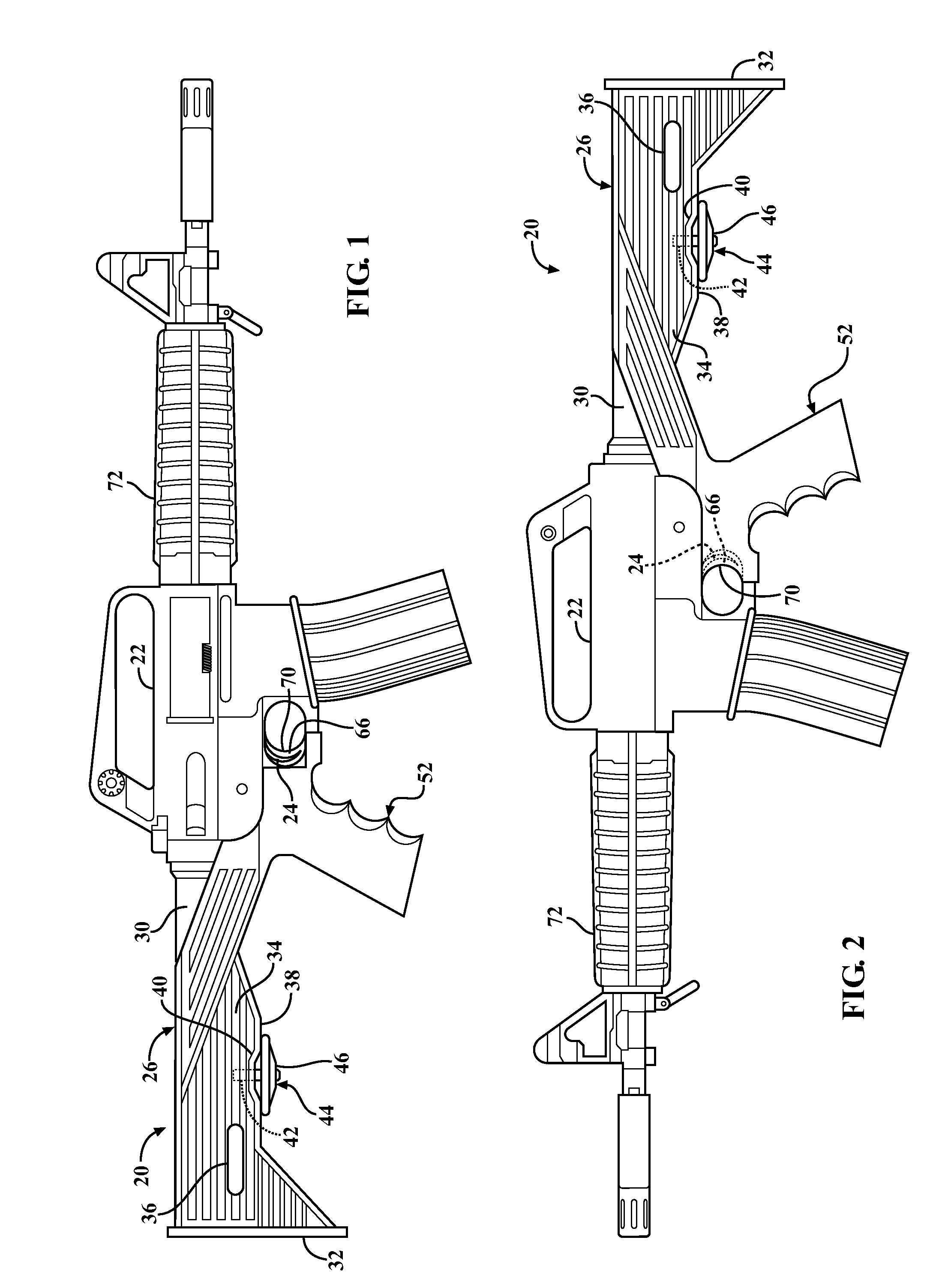
[0023]Referring to the Figures, wherein like numerals indicate corresponding parts throughout the several views, a first embodiment of a handle 20 for supporting the receiver and barrel portions of a semi-automatic firearm 22 having a trigger 24 is generally shown in FIG. 1.

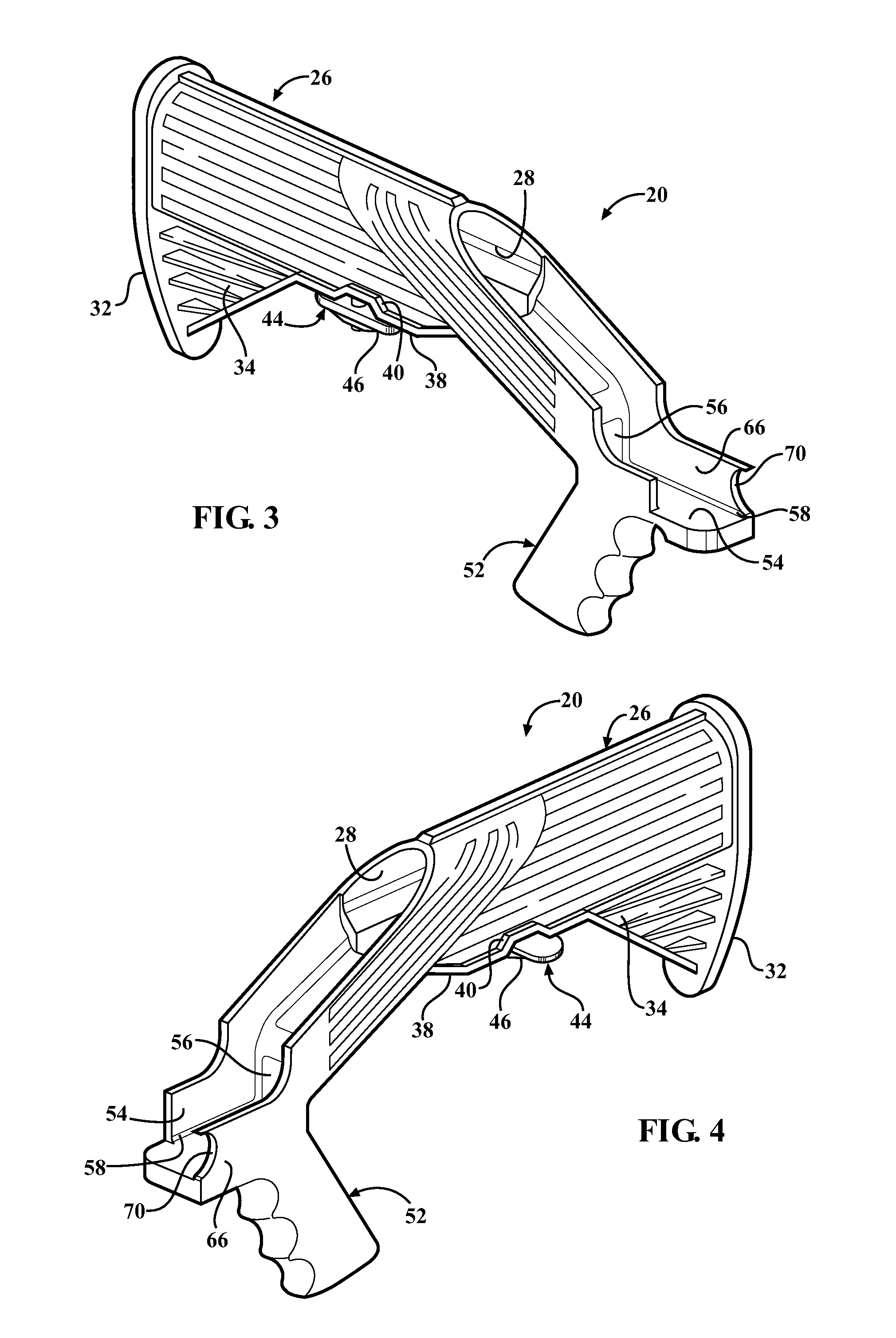
[0024]The first embodiment of the handle 20 is for firing a semi-automatic firearm 22, shown as an AR-15 in FIGS. 1 and 2, however, any suitable semi-automatic firearm may be used with minor modifications. The handle 20 includes a stock portion 26 (generally indicated) defining a buffer cavity 28 having a generally tubular shape for slidably receiving a buffer tube 30 of the semi-automatic firearm 22. Of course, the shape of the buffer cavity 28 will be modified to accommodate the particular type of semi-automatic firearm 22 used. One end of the stock portion 26 of the handle 20 presents a butt end 32 for abutting the shoulder of an operator when the firearm 22 is raised to a firing position. The stock portion 26...


PUM


Abstract

A handle (20) for rapidly firing a semi-automatic firearm (22) having a trigger (24). The handle (20) includes a grip portion (52) defining a channel (54). A block (60) that is connected to the firearm (22) is slidably disposed in the channel (54) for allowing longitudinal movement of the firearm (22) relative to the handle (20). The handle (20) also includes a trigger guard (66) disposed on one side of the trigger (24) and extending longitudinally forward of the trigger (24) by a predetermined distance (D) to an open end. The trigger guard (66) presents a finger rest (70) for placing a trigger finger (74) on the trigger guard (66). The trigger guard (66) restricts access to the trigger (24) until the firearm (22) is moved longitudinally forward by the predetermined distance (D) relative to the handle (20). The handle (20) also includes a lock (44) having an open position for allowing longitudinal movement of the firearm (22) relative to the handle (20) and a locked position for restricting longitudinal movement of the firearm (22) relative to the handle (20).

Description

CROSS REFERENCE TO RELATED APPLICATION[0001]This application claims the benefit of application Ser. No. 61 / 262,315 filed Nov. 18, 2009.BACKGROUND OF THE INVENTION[0002]1. Field of the Invention[0003]The present invention relates generally to firearms. Specifically, the present invention relates to a handle for attaching to the firearm to securely hold the firearm while rapidly firing and a method for firing the firearm with the handle.[0004]2. Description of the Prior Art[0005]Various techniques and devices have been developed to increase the firing rate of semi-automatic firearms. Many of these techniques and devices make use of the concept known as “bump firing”, which is the manipulation of the recoil of the firearm to rapidly activate the trigger. One such bump firing technique is known as the “belt loop” method. To execute the belt loop method, the operator first places the firearm next to his or her hip and hooks one finger through both the trigger mechanism and a belt loop in...

Claims


Application Information

Patent Timeline
Patent Type & Authority Patents(United States)
IPC IPC(8): F41C23/14
CPCF41C23/04F41C23/14F41C23/16F41C23/20
Inventor COTTLE, JEREMIAHCOMPTON, DAVID
Owner SLIDE FIRE SOLUTIONS
Why Eureka
Try Eureka