Waterproof case

a technology of waterproof cases and covers, applied in the direction of sealing, coupling device connections, caps, etc., can solve the problems of failure of electrical components, leakage of current or other undesirable problems, and achieve the effect of avoiding production of welding lines

Active Publication Date: 2013-07-02
YAZAKI CORP
View PDF8 Cites 2 Cited by
  • Summary
  • Abstract
  • Description
  • Claims
  • Application Information

AI Technical Summary

Benefits of technology

[0010]An object of the present invention is thus to provide a waterproof case which can prevent the ingress of the water into the waterproof case through the protection piece described above.
[0012]According to the first aspect of the prevent invention described above, the lower end surface of the protrusion of the peripheral wall of the other one of the case body and the cover is arranged on the upper end surface of the protection piece. Thus, this protrusion serves to cover an upward opening of a space formed between the protection piece and the peripheral wall of the other one of the case body and the cover. As a result, the water can be prevented from entering the waterproof case via the upward opening of the space between the protection piece and the peripheral wall of the other one of the case body and the cover.
[0014]According to the second aspect of the prevent invention described above, even if the water had entered the space between the protection piece and the peripheral wall of the other one of the case body and the cover, the water is directed to exit outside from the through hole. Thus, the ingress of the water into the waterproof case can be prevented even more reliably.
[0016]According to the third aspect of the prevent invention described above, the thick portion helps avoiding production of a welding line caused by providing the through hole.

Problems solved by technology

This may cause a failure in the electrical components or a leak of current or other undesirable problems.

Method used


Image

  • Waterproof case
  • Waterproof case
  • Waterproof case

Examples


Embodiment Construction

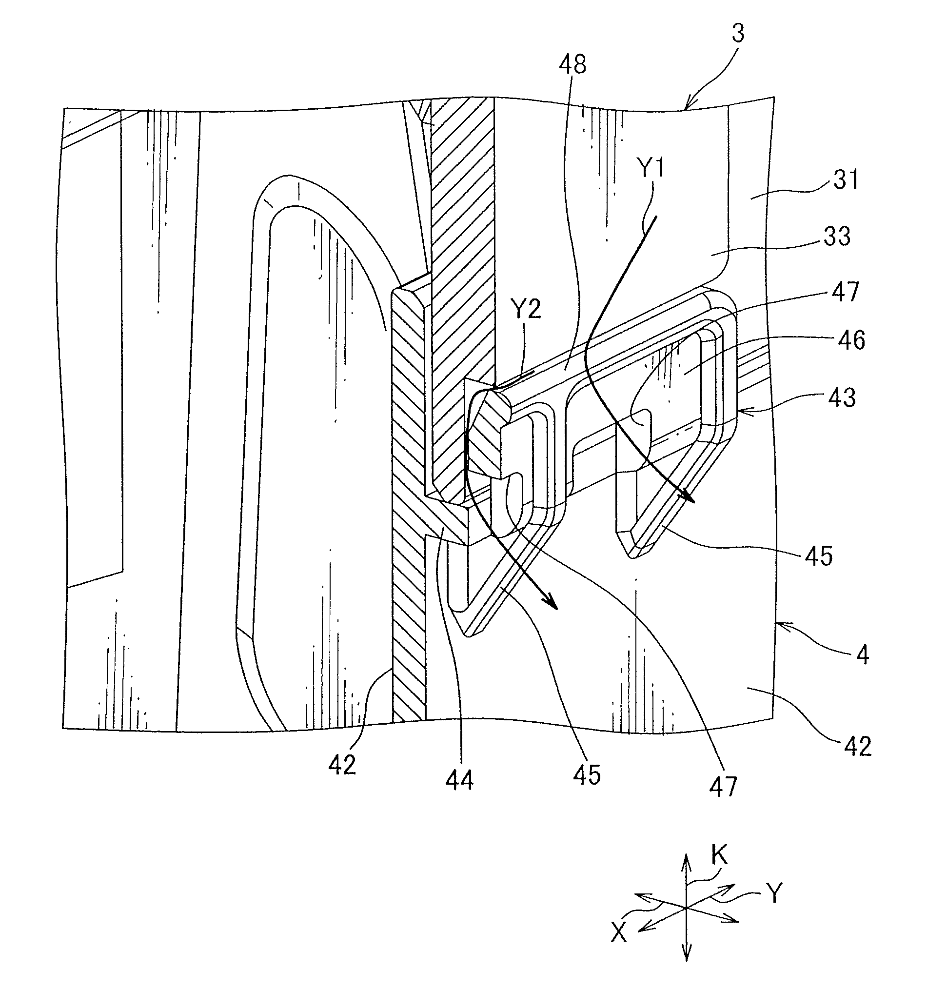
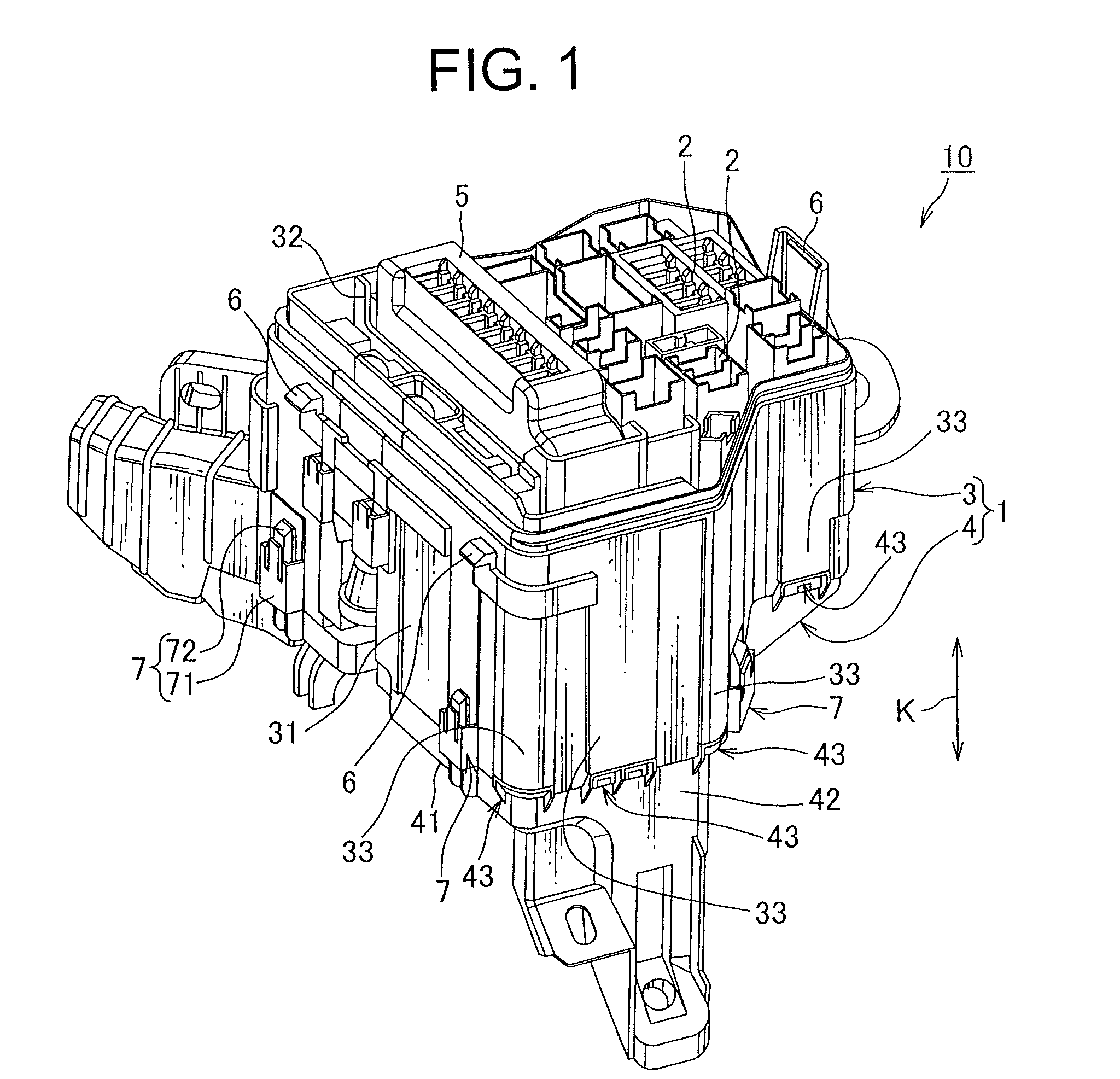
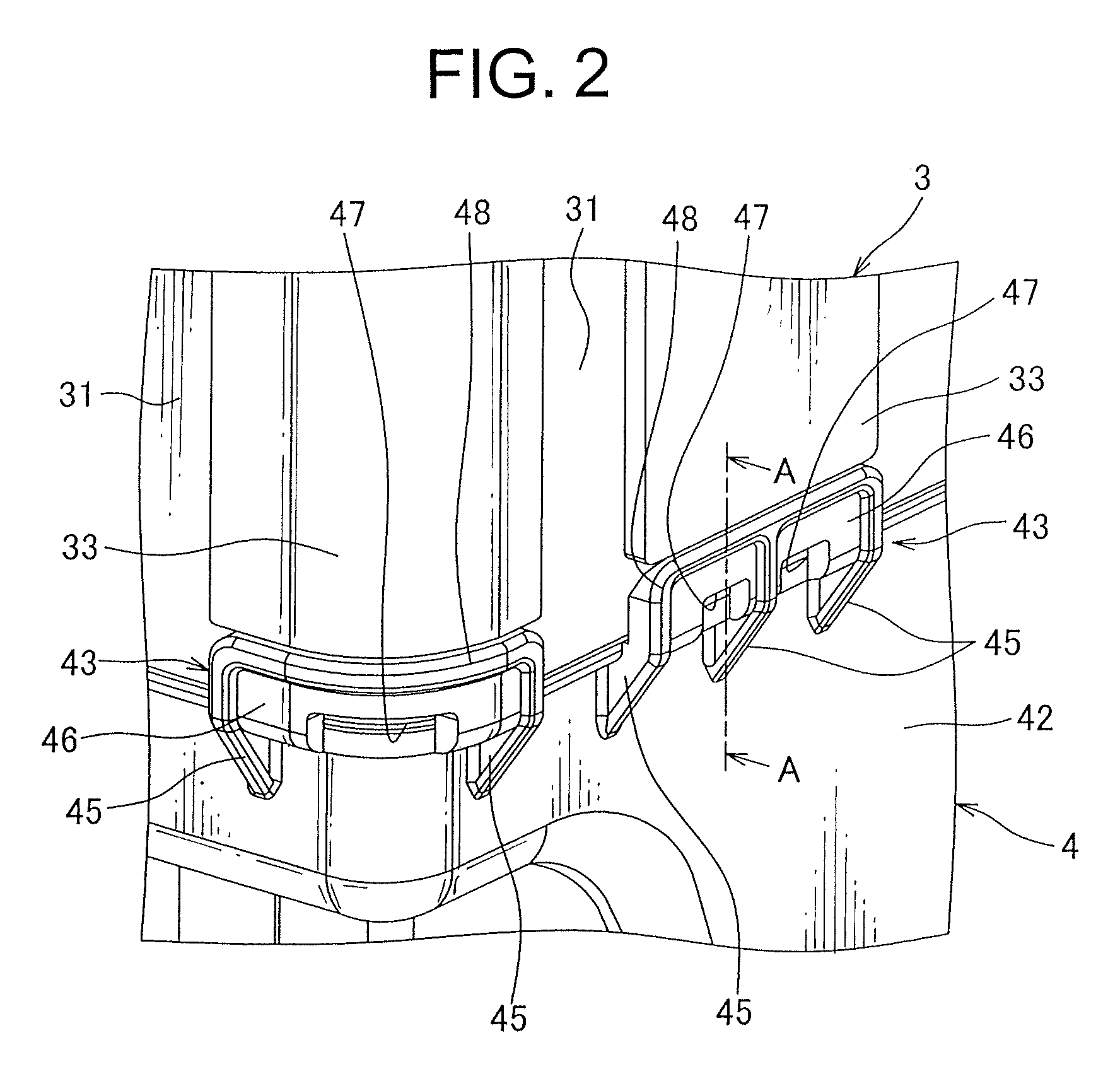
[0023]The following will describe a waterproof case of the present invention according to one embodiment in reference with FIGS. 1 through 3. FIG. 1 is an illustration of an electrical connection box having the waterproof case of the present invention according to one embodiment, in which an upper cover provided to the waterproof case is eliminated and not shown. FIG. 2 is an enlarged view of the waterproof case of FIG. 1. FIG. 3 is a cross-sectional view taken along a line A-A shown in FIG. 2.

[0024]Referring to FIG. 1, an electrical connection box 10 includes a waterproof case 1 forming a framework of the electrical connection box 10 and receiving a plurality of electrical components such as a connector of a wire harness, a relay, a fuse or an electricity distributor referred to as a power integration unit (hereinafter called a P / I unit) 5. The electrical connection box 10 is arranged to be attached to, for example, an engine room of a motor vehicle and serves to electrically conne...


PUM


Abstract

There is provided a waterproof case which prevents ingress of water into the waterproof case through a protection piece, including a case body formed into a rectangular tube-like shape with a peripheral wall thereof and a lower cover having a bottom wall covering a lower opening of the case body and a peripheral wall extending from the bottom wall. The peripheral wall of the body case is placed so as to cover the peripheral wall of the lower cover. The protection piece is provided at the peripheral wall of the lower cover so as to sandwich the peripheral wall of the case body with the peripheral wall of the lower cover to prevent the deformation of the peripheral wall of the lower cover. There is also provided a protrusion protruding from a surface of the peripheral wall of the case body on which the protection piece is placed.

Description

CROSS REFERENCE TO RELATED APPLICATION[0001]The priority application Japanese Patent Application No. 2010-153644 upon which this patent application is based is hereby incorporated by reference.BACKGROUND OF THE INVENTION[0002]1. Field of the Invention[0003]The present invention relates to a waterproof case to be attached to, for example, an engine room of a motor vehicle and which is suitable for use as an electrical connection box receiving therein electrical components such as a fuse or a relay.[0004]2. Description of the Related Art[0005]A motor vehicle is provided with an electrical connection box arranged at an suitable location within the vehicle to supply electricity from a source to a variety of electrical equipments mounted on the vehicle. There are a wide variety of electrical connection boxes depending on a type of the vehicle. One example of such electrical connection box is disclosed in Japanese Patent Application Publication No. 2004-64872 and is illustrated in FIGS. 4...

Claims


Application Information

Patent Timeline
Patent Type & Authority Patents(United States)
IPC IPC(8): B65D45/16H01R13/506
CPCB60R16/0238
Inventor SATO, KOKISUZUKI, YASUHITO
Owner YAZAKI CORP
Why Eureka
Try Eureka