Rearview mirror

a rearview mirror and mirror technology, applied in the field of rearview mirrors, can solve problems such as poor workability, and achieve the effect of improving assembly workability

Inactive Publication Date: 2012-09-13
MURAKAMI CORP
View PDF1 Cites 0 Cited by
  • Summary
  • Abstract
  • Description
  • Claims
  • Application Information

AI Technical Summary

Benefits of technology

[0015]The aspect of the present invention can achieve improved assembly workability.

Problems solved by technology

This requires a step of fitting the lamp unit in the mirror holder, while positioning the lamp unit relative to the mirror holder, thus posing a problem of poor workability.

Method used


Image

  • Rearview mirror
  • Rearview mirror
  • Rearview mirror

Examples


Embodiment Construction

[0020]A rearview mirror according to a preferred embodiment of the present invention will be described in detail below with reference to the drawings.

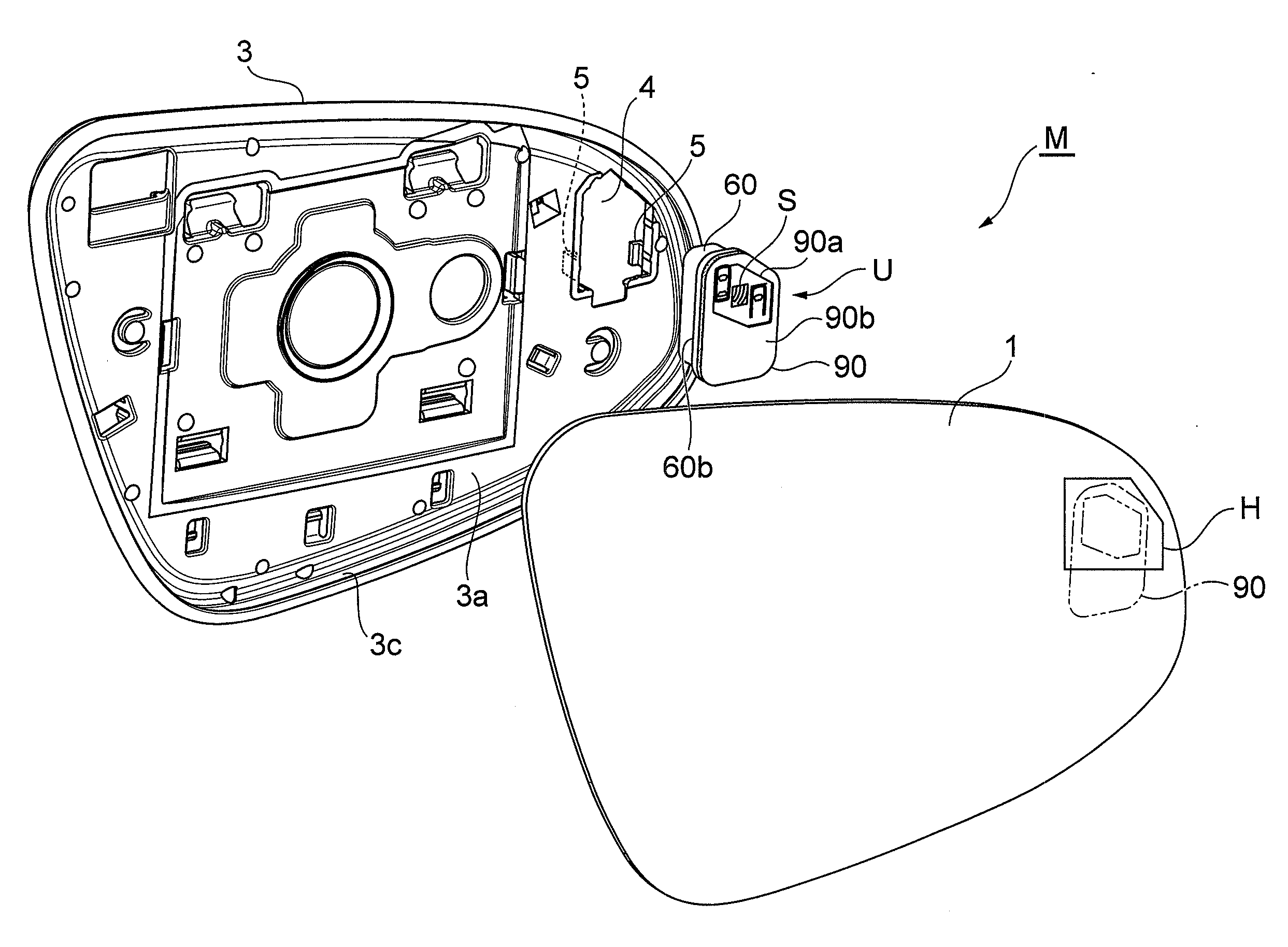
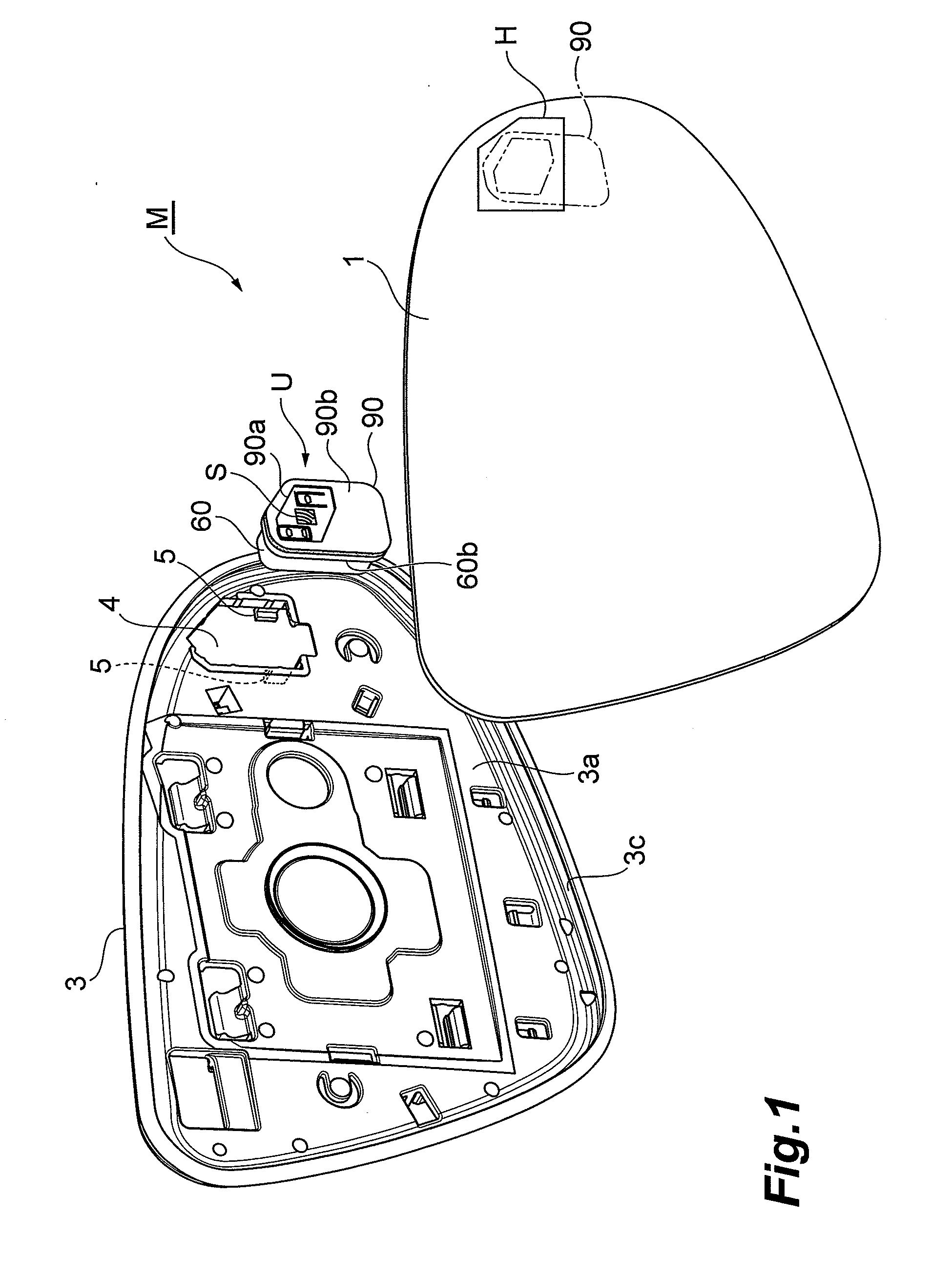
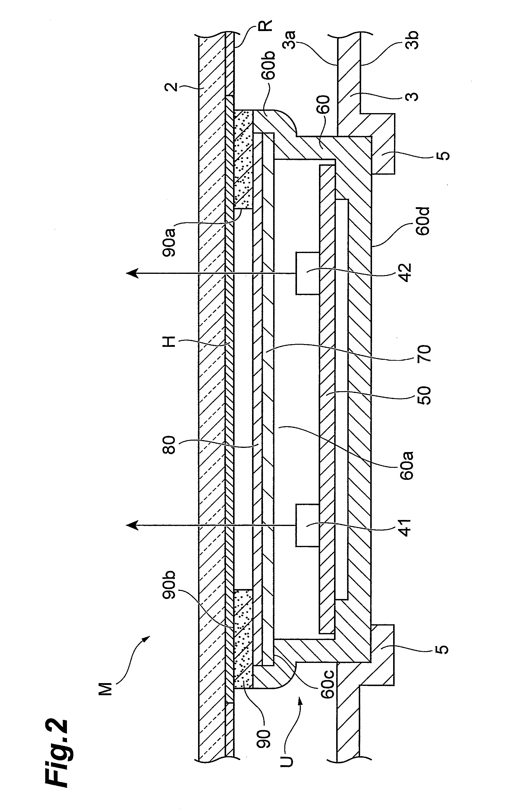
[0021]Referring to FIGS. 1 and 2, the door mirror for an automobile includes a reflective mirror 1 for viewing a rearward vehicle. The reflective mirror 1 is disposed so as to close an opening in a cup-shaped housing. A mechanism for moving the reflective mirror 1 is accommodated inside the housing. The reflective mirror 1 is transparent glass 2 having a back surface on which a reflective film R is vapor-deposited. The back surface of the reflective mirror 1 is covered in a resin mirror holder 3. A recess-shaped fit portion 3c in which a circumferential edge of the reflective mirror 1 is to be fitted is formed on a circumferential edge of the mirror holder 3. The reflective mirror 1 and the mirror holder 3 configure a mirror unit M.

[0022]In addition, a lamp unit U including a lead (not shown) is disposed on the back surface of the refl...


PUM


Abstract

An aspect of the present invention provides a rearview mirror designed to enhance assembly workability. When assembling a mirror unit of the rearview mirror, a lamp unit is dropped in an opening provided on a mirror holder from an inner surface side of the mirror holder in a condition in which side object detection symbols face upward. Thereafter, a circumferential edge of a reflective mirror is fitted into a recess-shaped fit portion of the mirror holder. The lamp unit is thus simply clamped and fixed between a lamp unit receiving portion (tab portions) and the reflective mirror. When the lamp unit is assembled in the mirror unit, therefore, adhesive is not used, so that workability is extremely good.

Description

BACKGROUND OF THE INVENTION[0001]1. Field of the Invention[0002]The present invention relates to a rearview mirror including a reflective mirror on which, for example, a warning is displayed.[0003]2. Related Background Art[0004]U.S. Pat. No. 6,264,353 is known as art in such a field. A rearview mirror disclosed in this publication includes a module (lamp unit) for making a reflective mirror display a turn signal. The module accommodates therein light-emitting diodes (LEDs) arrayed into a letter V. Tabs formed on the module are hooked through tab engagement onto snap retainers of a mirror holder for holding the reflective mirror. This results in the module being firmly fixed onto the mirror holder, so that a lens disposed in the module can be spaced apart from the reflective mirror.SUMMARY OF THE INVENTION[0005]However, the lamp unit is required to be fixed onto the mirror holder through cooperation between the tabs and the snap retainers. This requires a step of fitting the lamp uni...

Claims


Application Information

Patent Timeline
Patent Type & Authority Applications(United States)
IPC IPC(8): B60R1/02
CPCB60R1/02B60R1/12B60Q1/2665B60R2001/1215B60R1/1207
Inventor TAKAYANAGI, SHINYA
Owner MURAKAMI CORP
Why Eureka
Try Eureka