Gasket for electrical junction box of railcar and electrical junction box of railcar

a technology for gaskets and electrical junction boxes, which is applied in the direction of engine seals, electrical apparatus, mechanical apparatus, etc., can solve the problems of easy intrusion water may intrude into the inside of the electrical junction box, and the contact state between the box main body and the cover may become unstable, so as to improve the water tightness between the box main body and the cover.

Active Publication Date: 2017-02-28
KAWASAKI RAILCAR MFG CO LTD
View PDF5 Cites 1 Cited by
  • Summary
  • Abstract
  • Description
  • Claims
  • Application Information

AI Technical Summary

Benefits of technology

[0010]According to this configuration, the gasket for the electrical junction box of the railcar includes the small width portions and the large width portions, and the large width portions and the small width portions are alternately provided. With this, each of the large width portions contacts both side surfaces of the groove portion, and each of the small width portions are easily positioned at the center of the groove portion in the width direction. With this, a clearance between the small width portion and one of both side surfaces of the groove portion and a clearance between the small width portion and the other of both side surfaces of the groove portion are maintained so as to be substantially equal to each other. When the cover and the side wall portion of the box main body face each other, the deformation of the small width portions in the groove portion becomes uniform in the circumferential direction. Thus, a repulsive force of the gasket stabilizes. Therefore, water-tightness between the box main body and the cover is secured, and water can be prevented from intruding into the electrical junction box from the outer space. Since each of the large width portions contact both side surfaces of the groove portion, the gasket does not fall off from the groove portion. Further, since it becomes easy to position the small width portion of the gasket at the center of the groove portion in the width direction, an expansion margin is formed between the groove portion and the small width portion. With this, even if the electrical junction box is placed under a high-temperature circumstance during the operation of the railcar or the like, a case where excessive pressure acts on the box main body or the cover by the heat expansion of the gasket can be prevented. Thus, the electrical junction box can be prevented from cracking or the like.
[0012]According to this configuration, as with the above configuration, the pressure acting on the box main body or the cover by the heat expansion can be reduced while securing the water-tightness between the box main body and the cover. Further, when the cover and the box main body face each other, the projection of the large width portion overlaps the elastic member in a plan view. Therefore, the large width portion of the gasket contacts the elastic member, so that the water-tightness between the elastic member and the gasket can be secured.
[0014]According to this configuration, the large width portion including the projection having such a shape that the length of the projection in the circumferential direction of the gasket decreases as the projection extends toward the outer side of the small width portion in the width direction is fitted in the corner portion including the inflection point, that is, the meandering corner portion. Therefore, a contact area between the large width portion and the corner portion becomes small, so that pressure applied from the corner portion to the large width portion hardly influences the small width portion. With this, the small width portion of the gasket is easily positioned at the center of the meandering corner portion in the width direction, so that the water-tightness between the box main body and the cover can be improved.

Problems solved by technology

According to this electrical junction box, if the waterproofing between the box main body and the cover is incomplete, the water easily intrudes into the inside of the electrical junction box from outside.
However, if the gasket is fitted in the groove which includes not only straight portions but also curved and / or meandering portions, a contact state between the box main body and the cover may become unstable, and the water may intrude into the inside of the electrical junction box.
If the gasket is attached to the cover, the gasket may fall off from the cover when attaching the cover to the box main body.
However, the electrical junction box is exposed to the outer space, so that there is a possibility that when the electrical junction box is placed under a high-temperature circumstance during the operation of the railcar or the like, the gasket made of rubber expands by heat, and pressure generated by the heat expansion of the gasket is applied to the box main body or the cover, and as a result, the box main body or the cover deforms.

Method used


Image

  • Gasket for electrical junction box of railcar and electrical junction box of railcar
  • Gasket for electrical junction box of railcar and electrical junction box of railcar
  • Gasket for electrical junction box of railcar and electrical junction box of railcar

Examples


first embodiment

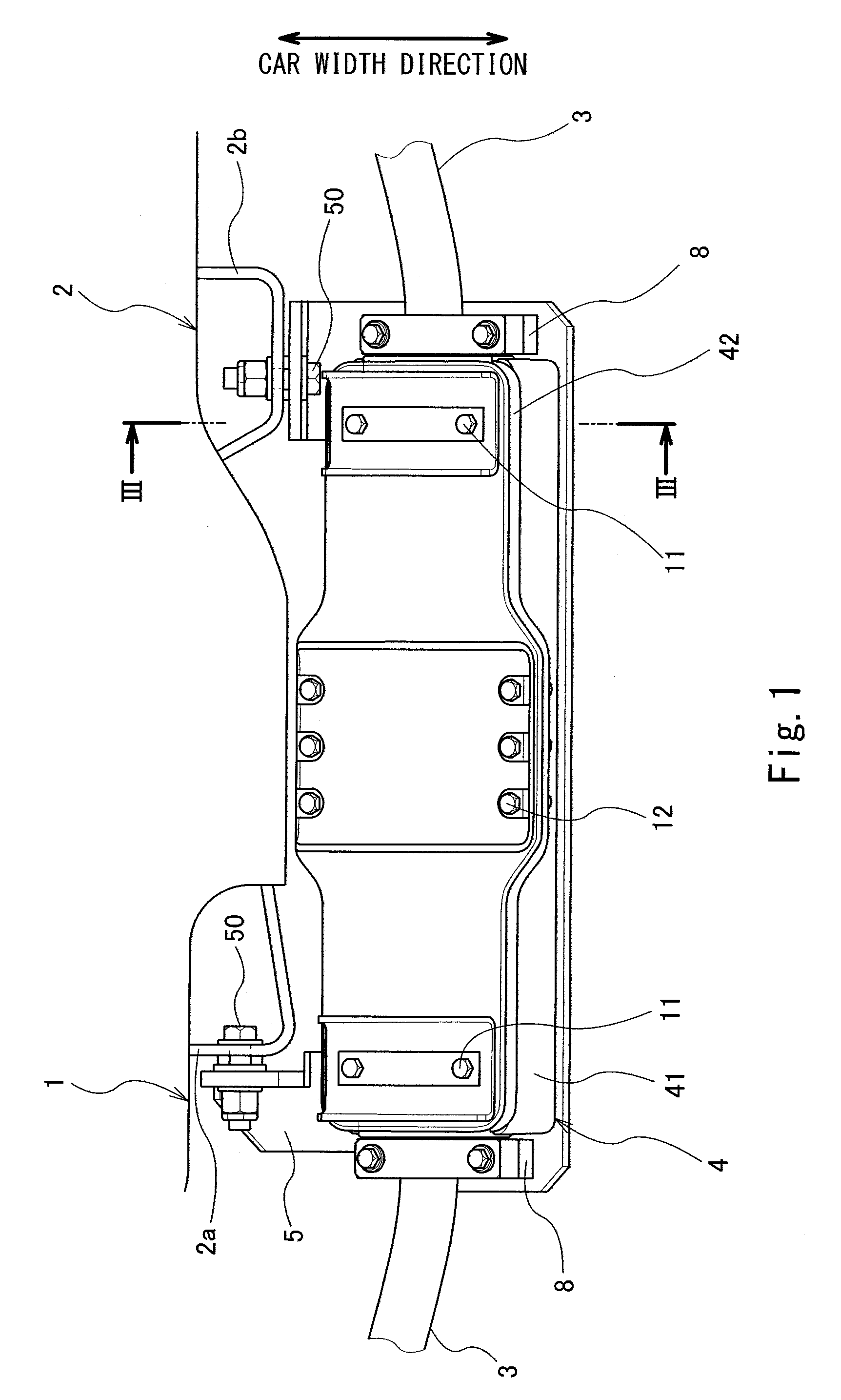
[0025]FIG. 1 is a diagram showing an electrical junction box 4 attached to a bogie 1 for a railcar, when viewed from above. The bogie 1 is provided with a motor as a power unit and a current collector for a third rail (both not shown). The current collector supplies electric power to a carbody through an electric cable 3. An end portion of the electric cable 3 is accommodated in the electrical junction box 4.

[0026]As shown in FIG. 1, the electrical junction box 4 includes a box main body 41 and a cover 42, which are made of resin such as plastic. The electrical junction box 4 has a substantially rectangular solid shape that is long in a car longitudinal direction. Guide members 8 configured to position the electric cable 3 are provided at both respective sides of the box main body 41 in the car longitudinal direction. The electrical junction box 4 is attached to an outer surface of a bogie frame 2 of the bogie 1 through mounting brackets 5 and is exposed to an outer space. The elect...

second embodiment

[0051]Next, an electrical junction box 14 according to the second embodiment will be explained. In the first embodiment, the gasket is provided at the cover. However, in the present embodiment, the gasket is provided at the box main body.

[0052]FIG. 7 is a schematic cross-sectional view showing the electrical junction box 14 of the railcar according to the second embodiment. As shown in FIG. 7, a groove portion 141d is formed on a contact surface P1 of a side wall portion 141b of a box main body 141 of the electrical junction box 14. The gasket 15 is fitted in the groove portion 141d of the box main body 141. When fixing a cover 142 to the box main body 141, the gasket 15 is pressed by the cover 142. The gasket 15 herein is the same in configuration as the gasket of the first embodiment.

[0053]According to the configuration explained as above, as with the first embodiment, when the cover 142 and the side wall portion 141b of the box main body 141 face each other, the deformation of th...

third embodiment

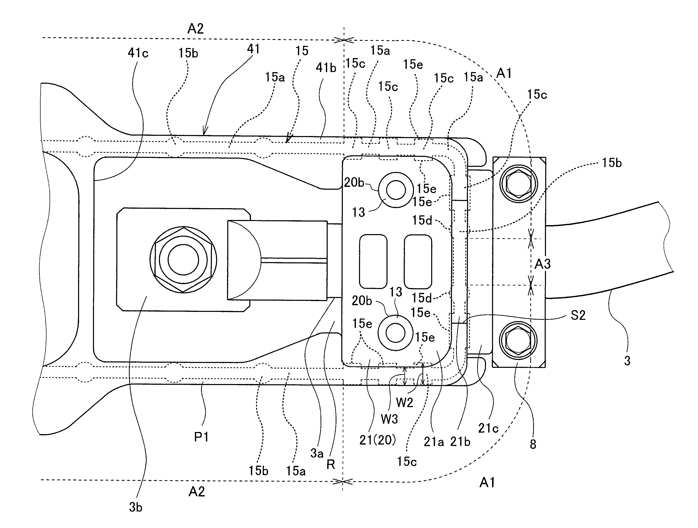
[0054]An electrical junction box 304 according to the third embodiment is an electrical junction box obtained by partially modifying the shape and configuration of the electrical junction box 4 according to the first embodiment. The following will mainly explain differences between the electrical junction box 304 of the third embodiment and the electrical junction box 4 of the first embodiment. FIG. 8 is a plan view showing a box main body 341 of the electrical junction box 304. As shown in FIG. 8, the electrical junction box 304 includes the box main body 341. A cover which is the same as the cover 142 of FIG. 7 is attached to the box main body 341. The box main body 341 includes a bottom wall portion 341a, a side wall portion 341b, and a dividing wall portion 341c. In a space R surrounded by the bottom wall portion 341a, the side wall portion 341b, and the dividing wall portion 341c, a stud terminal 310 projecting from a fuse box and an electrically conductive spacer 311 electrica...


PUM


Abstract

A gasket for an electrical junction box of a railcar is fitted in a groove portion formed on a contact surface of a side wall portion or a contact surface of a cover in the electrical junction box including: a box main body having the side wall portion defining an opening communicating with an outer space; and the cover closing the opening. Further, the gasket for the electrical junction box of the railcar includes: small width portions, a width of each of the small width portions being smaller than a width of the groove portion; and large width portions each having projections projecting toward both respective sides of the small width portion in a width direction and having a larger width than the width of the small width portions. The small width portions and the large width portions are alternately provided.

Description

CROSS REFERENCE TO RELATED APPLICATION[0001]The present application claims priority from Japanese Patent Application No. 2014-247602 filed on Dec. 8, 2014 with the Japan Patent Office, the disclosure of which is incorporated herein by reference in its entirety.TECHNICAL FIELD[0002]The present disclosure relates to a gasket for an electrical junction box of a railcar and the electrical junction box of the railcar.BACKGROUND[0003]In railcars, power supply from a carbody to a motor and power collection from a third rail (power supply rail) to the carbody by a current collector provided at a bogie are performed through electric cables. Since the carbody and the bogie are separated from each other at the time of maintenance, the electric cable is configured to be disconnectable at a connector or an electrical junction box. The connector or the electrical junction box is attached to a bogie frame of the bogie, and all of these components are exposed to an outer space.[0004]Therefore, if t...

Claims


Application Information

Patent Timeline
Patent Type & Authority Patents(United States)
IPC IPC(8): H02G3/08F16J15/06
CPCH02G3/088F16J15/06
Inventor HAMADA, MASAHIROFUKUMOTO, HIDEKIMIZUKAWA, TERUAKISAKAHIRA, MASAHIRONARITA, TOMOHIRO
Owner KAWASAKI RAILCAR MFG CO LTD
Why Eureka
Try Eureka