Upper denture release apparatus and method of use

a technology of upper dentures and dentures, which is applied in the field of upper denture release apparatus and method of use, can solve the problems of difficult upper denture removal, difficult cleaning, sleeping, etc., and achieves the effects of fast and easy upper denture removal, convenient cleaning, and convenient us

Active Publication Date: 2013-07-02
LAMEE MAURICE
View PDF17 Cites 7 Cited by
  • Summary
  • Abstract
  • Description
  • Claims
  • Application Information

AI Technical Summary

Benefits of technology

[0009]Accordingly, it is an object of the present invention to provide an upper denture release apparatus and method of use which is simple and effective to use. Design features allowing this object to be accomplished include a denture puller having an arm attached to a leg, a hook attached to an end of the arm, and a chin rest attached to the leg; and an upper denture having a notch sized to admit the hook. Advantages associated with the accomplishment of this object include faster and easier upper denture removal, even when the denture wearer suffers from arthritis.
[0010]It is another object of the present invention to provide an upper denture release apparatus and method of use which is adjustable in order to accommodate different denture wearer face sizes. Design features allowing this object to be accomplished include a denture puller having an arm attached to a leg, a hook attached to an end of the arm, arm length adjustment means, and a chin rest attached to the leg; and an upper denture having a notch sized to admit the hook. A benefit associated with the accomplishment of this object is the flexibility of application of the denture puller to different denture wearers' faces.
[0011]It is still another object of this invention to provide an upper denture release apparatus and method of use which is quick and easy to use. Method steps enabling the accomplishment of this object include resting a wearer's chin on the chin rest, inserting the hook into the notch, and opening the wearer's mouth, thus pulling the upper denture off the wearer's upper gum. An advantage associated with the realization of this object is virtually effortless removal of a top denture.
[0012]It is yet another object of this invention to provide an upper denture release apparatus and method of use which is economical to produce. Design features allowing this object to be achieved include the use of components and materials which are readily available. Benefits associated with reaching this objective include reduced cost, and hence increased availability.

Problems solved by technology

A delicate balance must be achieved between the denture / implant fit being so tight as to render removal of the denture excessively difficult, and the denture / implant fit being too loose and not properly retaining the denture in position.
Even where the correct balance is struck, it can be difficult to remove upper dentures for cleaning, sleeping, etc., especially where the individual is arthritic, or suffers from some other debilitating condition of the hands.
These are generally complex and hence difficult to use, and expensive.

Method used


Image

  • Upper denture release apparatus and method of use
  • Upper denture release apparatus and method of use
  • Upper denture release apparatus and method of use

Examples


Embodiment Construction

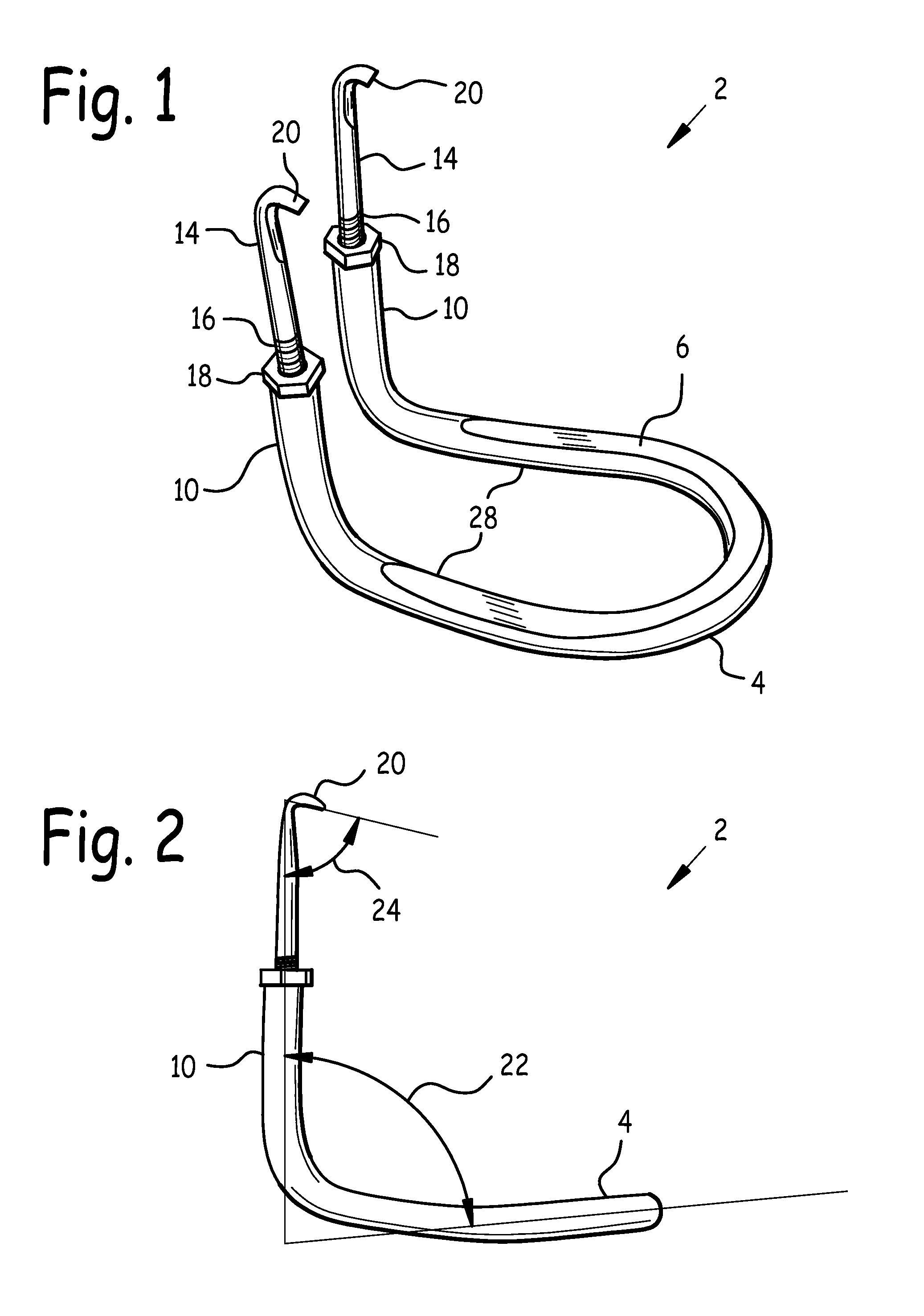
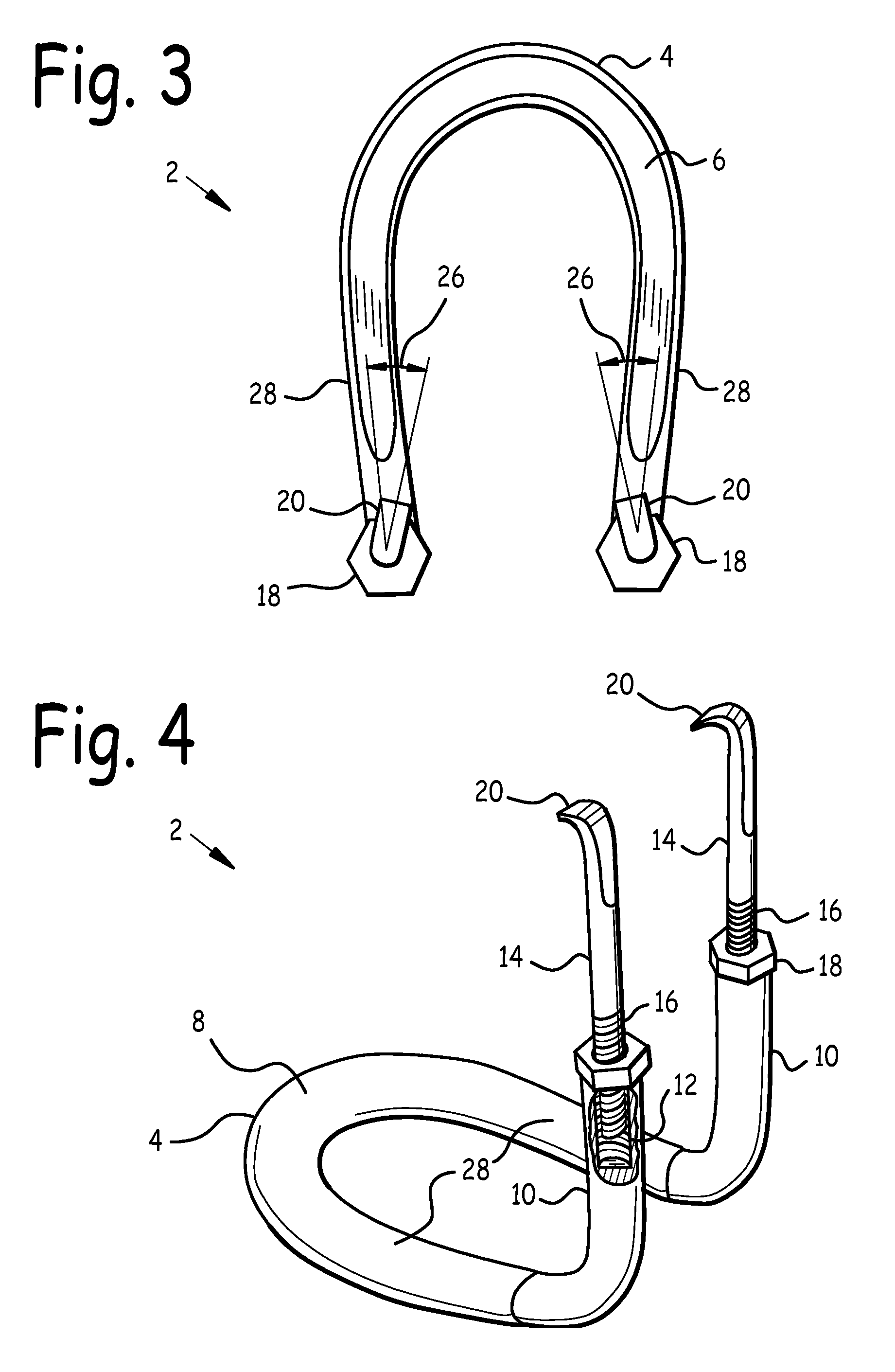
[0026]Referring now to FIG. 1, a right quarter side isometric view of denture puller 2, and FIG. 2, a right side view of denture puller 2, we may observe that denture puller 2 includes arms 10 rigidly attached to legs 28 at arm angle 22. Chin rest 4 is attached to an end of legs 28 opposite arms 10, and hook 20 is attached to an end of each arm 10 opposite legs 28. Chin rest 4 may be flattened at its upper surface to form chin rest land 6, upon which the chin of a wearer will rest, in order to make the use of denture puller 2 more comfortable to the wearer.

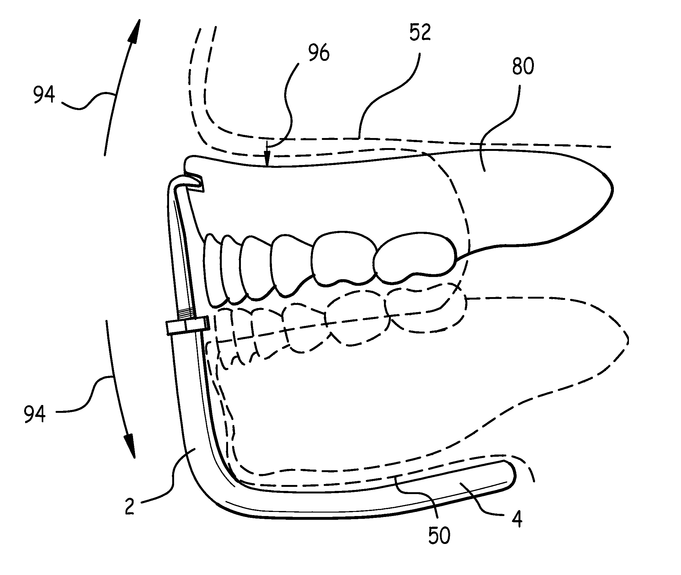
[0027]Denture puller 2 engages with notch(es) 82 in upper denture 80 to remove upper denture 80, as is illustrated in FIGS. 7-10. In order to securely engage denture puller 2 with notch 82, it was experimentally determined that a hook declination angle 24 of 75 degrees±15 degrees was optimal. Hook declination angle 24 is the angle between hook 20 and arm 10 when denture puller 2 is viewed from the side, as shown in FIG. 2.

[0028]De...


PUM


Abstract

An upper denture release apparatus and method of use. A denture puller has a chin rest, arm attached to the chin rest, and a hook attached to an end of the arm opposite the chin rest. An upper denture has a notch sized and located to admit the hook when a wearer's chin rests on the chin rest. The method includes the steps of resting a wearer's chin on the chin rest, inserting the hook into the upper denture notch, and opening the wearer's mouth, thus pulling the upper denture off the wearer's upper gum. Arm length adjustment is shown, whereby the denture puller may be adjusted to fit differently-sized upper denture wearers. Preferred hook declination, hook toe, arm and notch floor angles are disclosed.

Description

BACKGROUND OF THE INVENTION[0001]1. Field of the Invention[0002]This invention relates to dentures, and in particular to an upper denture release apparatus and method of use.[0003]2. Background of the Invention[0004]Dentures, also referred to as false teeth, are used to replace missing teeth, which may include all upper or lower teeth. Loss of teeth necessitating use of a denture may be due to a variety of causes including dental disease such as periodontal disease or tooth decay. Other causes of tooth loss include malnutrition, dentinogenesis imperfecta, trauma, or drug use.[0005]Modern dentures are held in place primarily by suction between the denture and the surface of the underlying gum. It is therefore important that the border seal around the perimeter of the denture to the underlying gum be continuous around its complete length so as to preserve the suction between the denture and the gum.[0006]Dentures are also retained in place by means of implant posts which are implanted...

Claims


Application Information

Patent Timeline
Patent Type & Authority Patents(United States)
IPC IPC(8): A61C3/00
CPCA61C3/00A61C3/162A61C13/01A61C13/12
Inventor LAMEE, MAURICE
Owner LAMEE MAURICE
Why Eureka
Try Eureka