Push-up / chin-up exercise assembly

a technology of push-up and chin-up, which is applied in the field of push-up/chin-up exercise assembly, can solve the problems of expensive and space-consuming for one to obtain all of the equipment needed, and the user's range of motion is more limited

Inactive Publication Date: 2013-07-02
LIFELINE PROD LLC
View PDF22 Cites 5 Cited by
  • Summary
  • Abstract
  • Description
  • Claims
  • Application Information

AI Technical Summary

Benefits of technology

[0009]The grip support struts 118 preferably have lengths bending over the grip base upper section 104 toward the inner grip base side 110, with the grip support struts 118 defining a grip mouth 122 between the grip base 102, the grip support struts 118, and the grip 120. This grip mouth 122 is open from the inner grip base side 110 (i.e., between the grip support struts 118 and the inner grip base side 110) and between the right and left grip base sides 114 and 116. As a result, the grip base 102, the grip support struts 118, and the grip 120 have a hook-like shape wherein the grip mouth 122 defines the mouth of the hook, whereby hanging structure on a door or other portions of the surrounding environment can be received within the grip mouth 122 to suspend the exercise handle 100 above the floor in the orientation shown in FIGS. 1-5. The grip 120 is preferably situated to extend between the grip support struts 118 along an axis located at or near a plane situated halfway between the opposing inner and outer grip base sides 110 and 112, so that the grip 120 is centrally located on the exercise handle 100, thereby making the exercise handle 100 resistant to tipping when it is used for push-ups. At the same time, the bent / curving orientation of the grip support struts 118 allows more free space for the user in the direction of the inner grip base side 110: when the inner grip base side 110 faces toward the user's body, the grip support struts 118 are well clear of the path of travel of the user's wrists / forearms during push-ups, even where the grips 120 are oriented nearly perpendicular to the user's body.
[0010]Optionally, the grip base lower section 106 (seen in FIG. 2) may be rotatable with respect to the grip base upper section 104 about an axis of rotation, such that the grip base upper section 104 can pivot with respect to the grip base lower section 106 (and the floor) when a user performs push-ups. The grip base upper and lower sections 104 and 106 are also preferably lockable with respect to each other to prevent their relative rotation when desired. A preferred way of providing such lockability is shown in FIG. 6, which shows the exercise handle 100 bisected between its right and left grip base sides 114 and 116. The grip base upper section 104 is shown with an annular upper bearing race 124 which is rotatably engaged to an annular lower bearing race 126 on the grip base lower section 106, allowing the grip base upper section 104 to rotate with respect to the grip base lower section 106. The grip base lower section 106 includes a series of protruding members 128 arrayed about the axis of rotation. The grip base upper section 104 then includes a rotatable member 130 (also seen well in FIG. 5) wherein selective rotation of the rotatable member 130 situates at least a portion of the rotatable member 130—e.g., the descending annular wall 132, which only extends about a portion of the circumference of the rotatable member 130 (e.g., 180 degrees)—within a path of travel of the protruding members 128 when the grip base lower section 106 rotates with respect to the grip base upper section 104. As a result, the rotatable member 130 can be rotated to selectively interfere with the travel of the protruding members 128, and thereby hinder rotation of the grip base lower section 106 with respect to the grip base upper section 104.
[0011]As seen (for example) in FIG. 1-4, a grip passage 134 extends within the grip 120 between opposing grip passage openings (also depicted at 134), whereby a flexible elongated member (e.g., a strap or elastic cable) may be inserted to extend through the grip passage and out the grip passage openings 134. Such elongated members can be put to a variety of uses, as discussed in greater detail below. As one example, an elastic cable can be inserted through the grip passages 134 of a pair of exercise handles 100, and its ends can then be fastened together to form a loop having a length strung through the exercise handles 100. A user can then perform push-ups with the elastic cable situated behind his / her back, with the cable thereby increasing the resistance experienced by the user.

Problems solved by technology

In contrast, without push-up handles, the user's range of motion is more limited since the user naturally cannot move his / her chest and face past the floor.
Chin-ups are also popular owing to their simplicity and low expense, though they are limited by their requirement for an easily graspable overhead structure (and for sufficient clearance above the structure).
A common complaint in the exercise field is that is generally expensive and space-consuming for one to obtain all of the equipment needed for one to completely exercise his / her entire body, or even his / her main muscle groups.

Method used


Image

  • Push-up / chin-up exercise assembly
  • Push-up / chin-up exercise assembly
  • Push-up / chin-up exercise assembly

Examples


Embodiment Construction

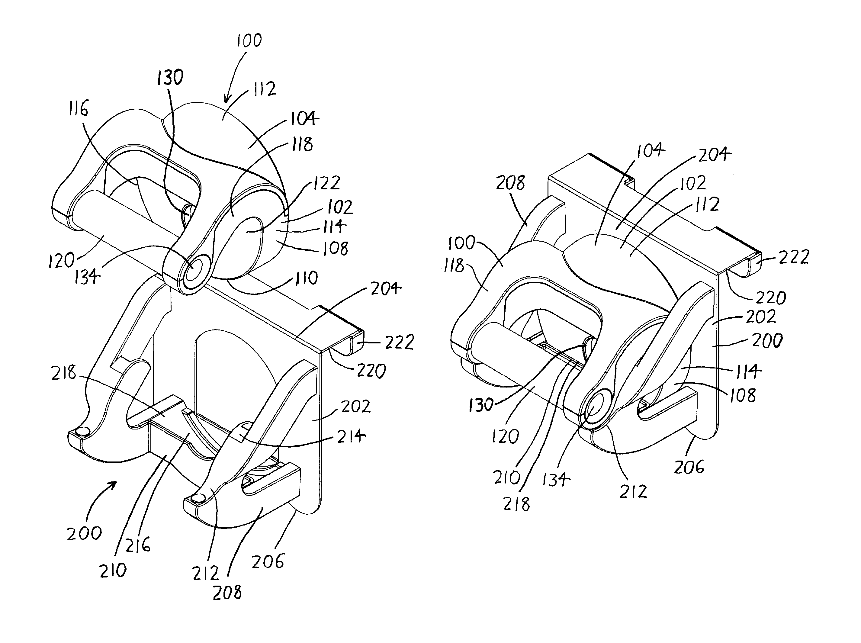
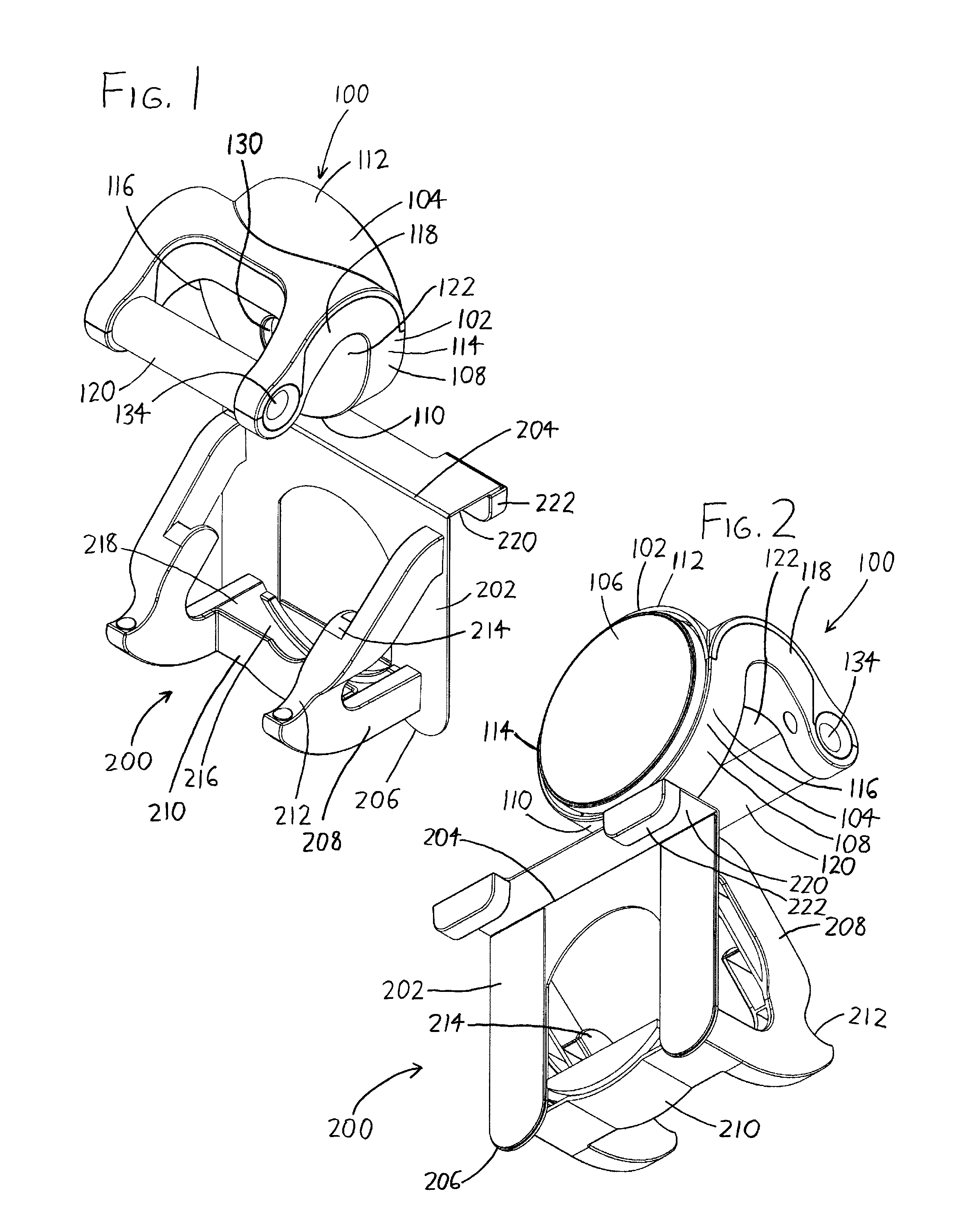
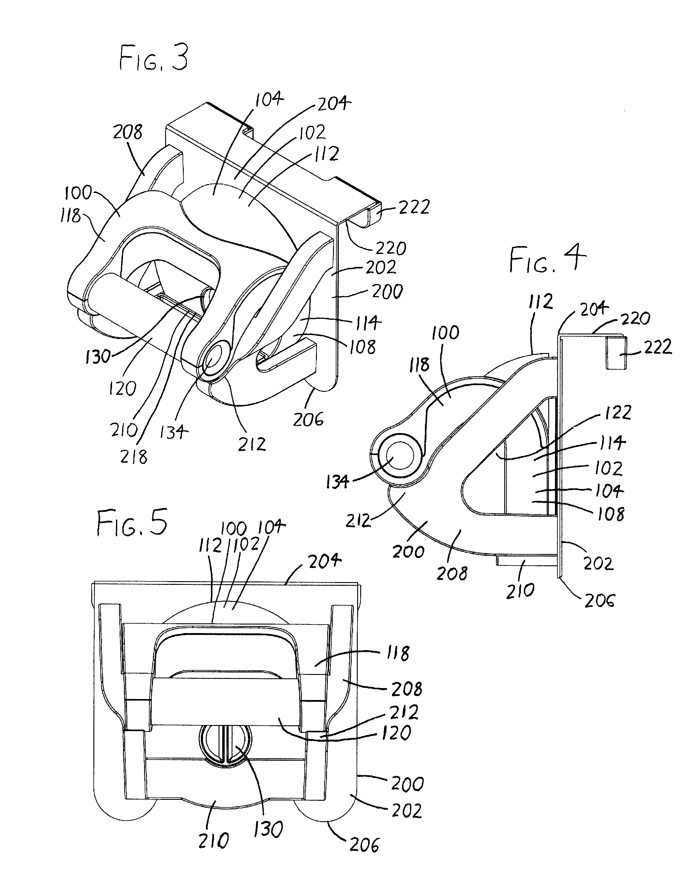
[0021]Expanding on the discussion above, the mounting means for mounting the cradle 200 to surrounding environment—such as to a door—can assume a wide variety of forms other than those discussed above, such as fasteners (e.g., bolts which extend to surrounding environment such as a wall); apertures for complementarily receiving structure situated on surrounding environment (e.g., hanging holes for receiving a hook or bolt head extending from surrounding environment such as a wall); clamps for engaging doorframes, bars, or other structure which presents clamping surfaces; or hooks, clips, straps / cords, or other structure allowing the cradle 200 to be hooked, clipped, tied, or otherwise affixed to surrounding environment. Most preferably, the cradle 200 is mountable to a door, with the mounting means being specially configured to mount the cradle 200 atop a door. As noted previously, a preferred form of such a door mounting means includes an extension 220 which is configured to rest a...


PUM


Abstract

An exercise assembly includes an exercise handle with a grip base suitable for resting on a floor, and a grip elevated above the grip base. A user can situate the grip bases of a pair of the exercise handles on the floor, grasp their grips, and then perform push-ups. The grip bases can also be mounted to the top of a door or to other overhead structure, and the user can then grasp their grips to perform chin-ups. Preferably, this is done by providing a cradle which mounts to the door or other overhead structure, wherein the exercise handles may be firmly (but removably) nested into the cradles to mount them to the structure. The exercise handles may also bear passages or attachments for receiving elastic (or inelastic) cables for use in performing further exercises.

Description

CROSS-REFERENCE TO RELATED APPLICATIONS[0001]This application claims priority under 35 USC §119(e) to U.S. Provisional Patent Application No. 61 / 121,305 filed 10 Dec. 2008, the entirety of which is incorporated by reference herein.FIELD OF THE INVENTION[0002]This document concerns an invention relating generally to exercise devices, and more specifically to devices which assist with the performance of push-ups and / or chin-ups.BACKGROUND OF THE INVENTION[0003]A push-up is a common strength training exercise wherein the person exercising lies face down in a horizontal position, and then pushes against the floor with his / her arms to raise his / her body, followed by relaxation of the arms to lower his / her body. Push-ups are popular because they do not require equipment, and can be performed nearly anywhere. However, in recent years, push-up handles have come into common use: handles which may be grasped by users while performing push-ups, and which extend downwardly to enlarged bases whi...

Claims


Application Information

Patent Timeline
Patent Type & Authority Patents(United States)
IPC IPC(8): A63B23/12A63B21/068A63B21/08
CPCA63B21/16A63B23/12A63B21/1645A63B23/1218A63B23/1236A63B23/1209A63B21/4035
Inventor HINDS, ROBERT S.POLINSKY, GLENNROLLINS, RAYSTEPHENSON, JOHNSOTIS, WILLIAM
Owner LIFELINE PROD LLC
Why Eureka
Try Eureka