Convertible surgical clip applier system

a clip applier and surgeon technology, applied in the field of surgical clip appliers, can solve the problems of increased cost of a given procedure, increased operating room space, and misalignment of clip edges

Inactive Publication Date: 2013-07-02
APPL MEDICAL RESOURCES CORP
View PDF42 Cites 139 Cited by
  • Summary
  • Abstract
  • Description
  • Claims
  • Application Information

AI Technical Summary

Problems solved by technology

This not only increased the cost of a given procedure but also consumed additional space among the instruments in the operating room.
It is this autoclaving procedure which has often resulted in bending or otherwise damaging the jaws, ultimately resulting in clip misalignment and a general inability to receive and apply the clip.

Method used


Image

  • Convertible surgical clip applier system
  • Convertible surgical clip applier system
  • Convertible surgical clip applier system

Examples


Embodiment Construction

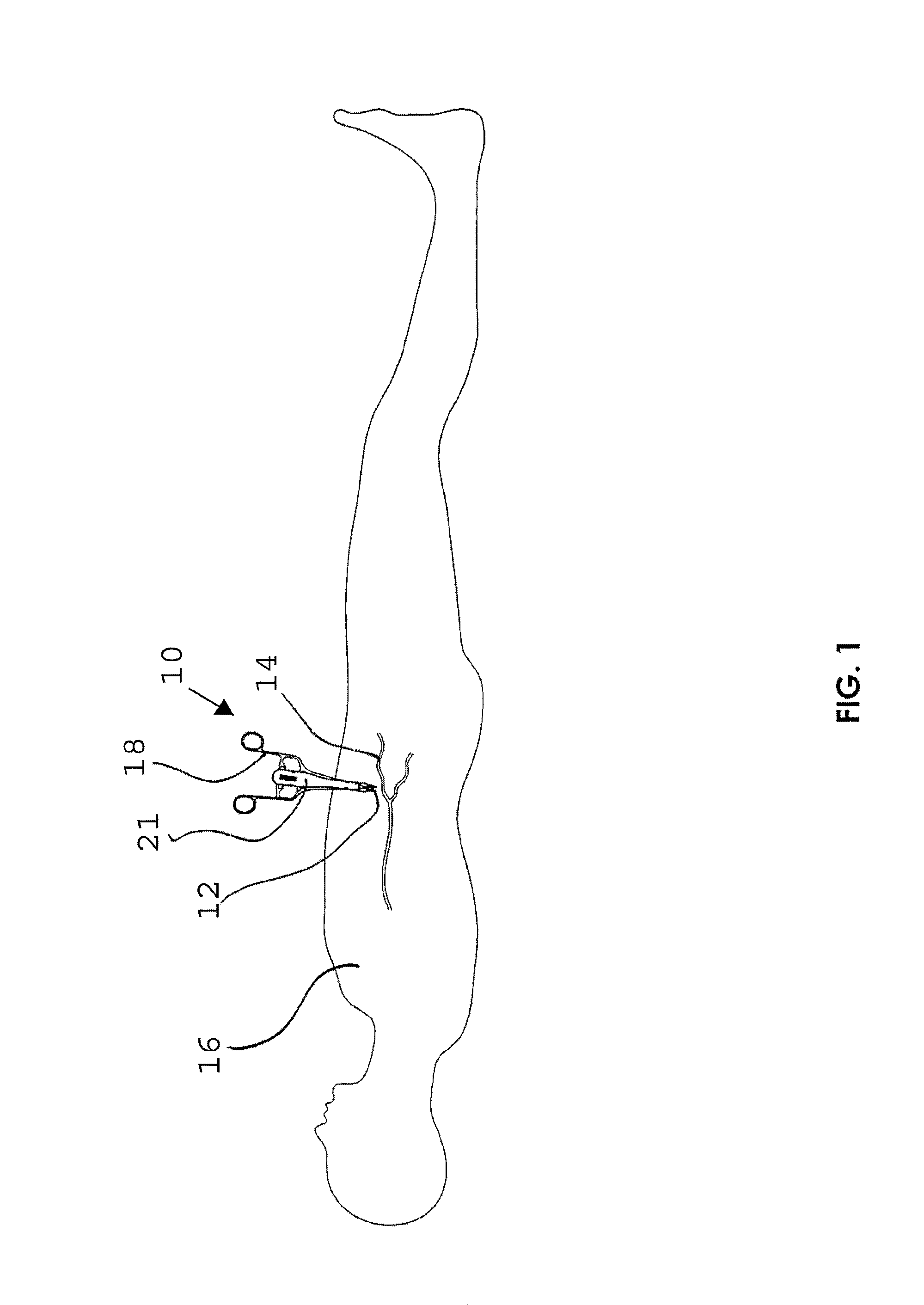
[0020]The surgical clip applier is illustrated in FIG. 1 and designated by the reference numeral 10. In this view, the clip applier 10 is operatively disposed to apply a clip 12 to a blood vessel 14 in the leg of a patient 16. The clip applier 10 includes a reusable handle assembly 18 and a disposable jaw assembly 21.

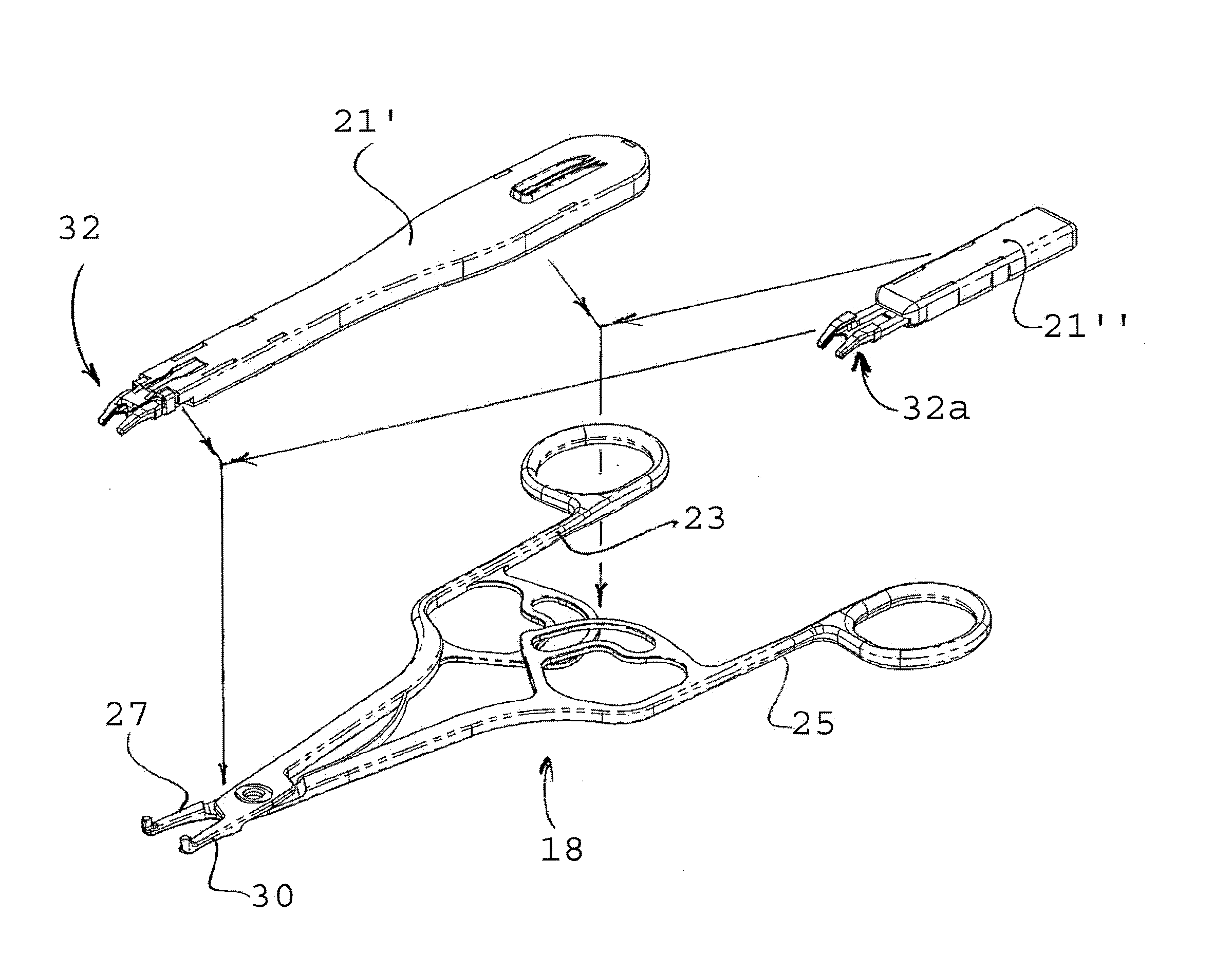
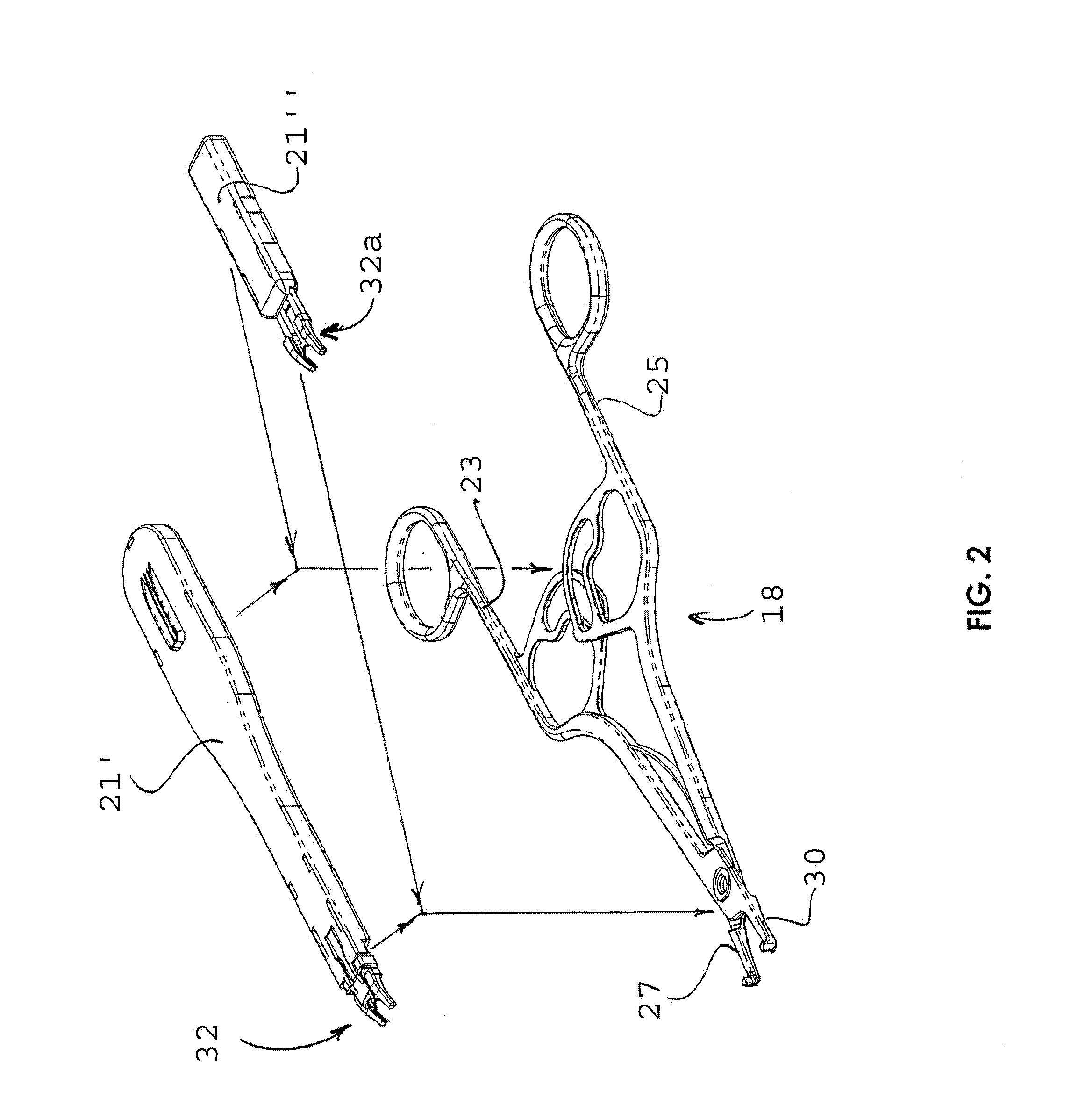
[0021]As best illustrated in the embodiment of FIG. 2, the handle assembly 18 will typically include a pair of handles 23 and 25 which control a pair of arms 27 and 30 in a scissors configuration. The jaw assembly 21 can be provided in various forms to facilitate a particular operative procedure. For example, the jaw assembly 21 may be provided in the form of a multiple-fire clip assembly 21′ or a single-fire clip assembly 21″. These two assemblies 21′ and 21″ can be alternatively attached to the handle assembly 18 as illustrated in FIG. 2.

[0022]An advantage of this convertibility is appreciated when one recognizes that the handle assembly 18 can be made reusable while ...


PUM


Abstract

A surgical clip applier includes a handle assembly, a first clip assembly, and a second clip assembly. The first clip assembly is adapted to receive only a single clip while the second clip assembly is adapted to receive multiple clips. The handle assembly is sized and configured to receive the first clip assembly or the second clip assembly. A jaw assembly includes a pair of jaws each with an elongate support arm, and a bridge holding the jaws in an aligned relationship. A housing has a fixed relationship with the bridge while permitting movement of the jaws between an open and a closed state. A coupling attaches the housing to the handle assembly. An associated method of operation includes the step of removing one of the single clip jaw assembly and the multiple clip-jaw assembly, disposing of the one jaw assembly while mounting the other jaw assembly on the handle.

Description

BACKGROUND OF THE INVENTION[0001]1. Field of the Invention[0002]This invention relates generally to surgical clip appliers and more specifically to clip appliers having a handle assembly in a scissors configuration.[0003]2. Discussion of the Relevant Art[0004]Surgical clips are commonly used to occlude body conduit such as blood vessels. In the past, clip appliers have been used to place the clip in an open state over the blood vessel and then to crimp the clip to a closed state thereby pinching and holding the vessel in an occluded configuration.[0005]In some cases, the clip appliers are adapted to work with only one clip at a time. A clip is manually placed between jaws of the clip applier and crimped onto the blood vessel before a second clip is manually loaded into the applier. Such devices are commonly referred to as single-fire clip appliers.[0006]By comparison, multiple clips have been housed in a clip cartridge, which is then mounted on a handle assembly. Operation of the ha...

Claims


Application Information

Patent Timeline
Patent Type & Authority Patents(United States)
IPC IPC(8): A61B17/10A61B17/00A61B17/122A61B17/128A61B17/28
CPCA61B17/1222A61B17/128A61B17/2812A61B2017/0023A61B2017/0046A61B2017/2845A61B2017/2916
Inventor VANDENBROEK, FRANSNGUYEN, LUONG
Owner APPL MEDICAL RESOURCES CORP
Why Eureka
Try Eureka