Image forming apparatus and method using different transfer voltages when recording material is heated in different image forming modes using different numbers of heating device

a technology of image forming apparatus and heating device, which is applied in the direction of electrographic process apparatus, instruments, optics, etc., can solve the problem of sometimes improper transfer voltage applied to the transferring means

Inactive Publication Date: 2013-07-02
CANON KK
View PDF8 Cites 4 Cited by
  • Summary
  • Abstract
  • Description
  • Claims
  • Application Information

AI Technical Summary

Benefits of technology

[0005]The object of the present invention is to provide an image forming apparatus which can satisfactorily transfer a toner image even if it is the case where a recording material which already has a toner image fixed by passing through a plurality of heating portions is resupplied to the transfer portion.

Problems solved by technology

For this reason, when the toner image is transferred after the recording material is resupplied to the transfer portion, a transfer voltage applied to the transferring means is sometimes improper.

Method used


Image

  • Image forming apparatus and method using different transfer voltages when recording material is heated in different image forming modes using different numbers of heating device
  • Image forming apparatus and method using different transfer voltages when recording material is heated in different image forming modes using different numbers of heating device
  • Image forming apparatus and method using different transfer voltages when recording material is heated in different image forming modes using different numbers of heating device

Examples


first embodiment

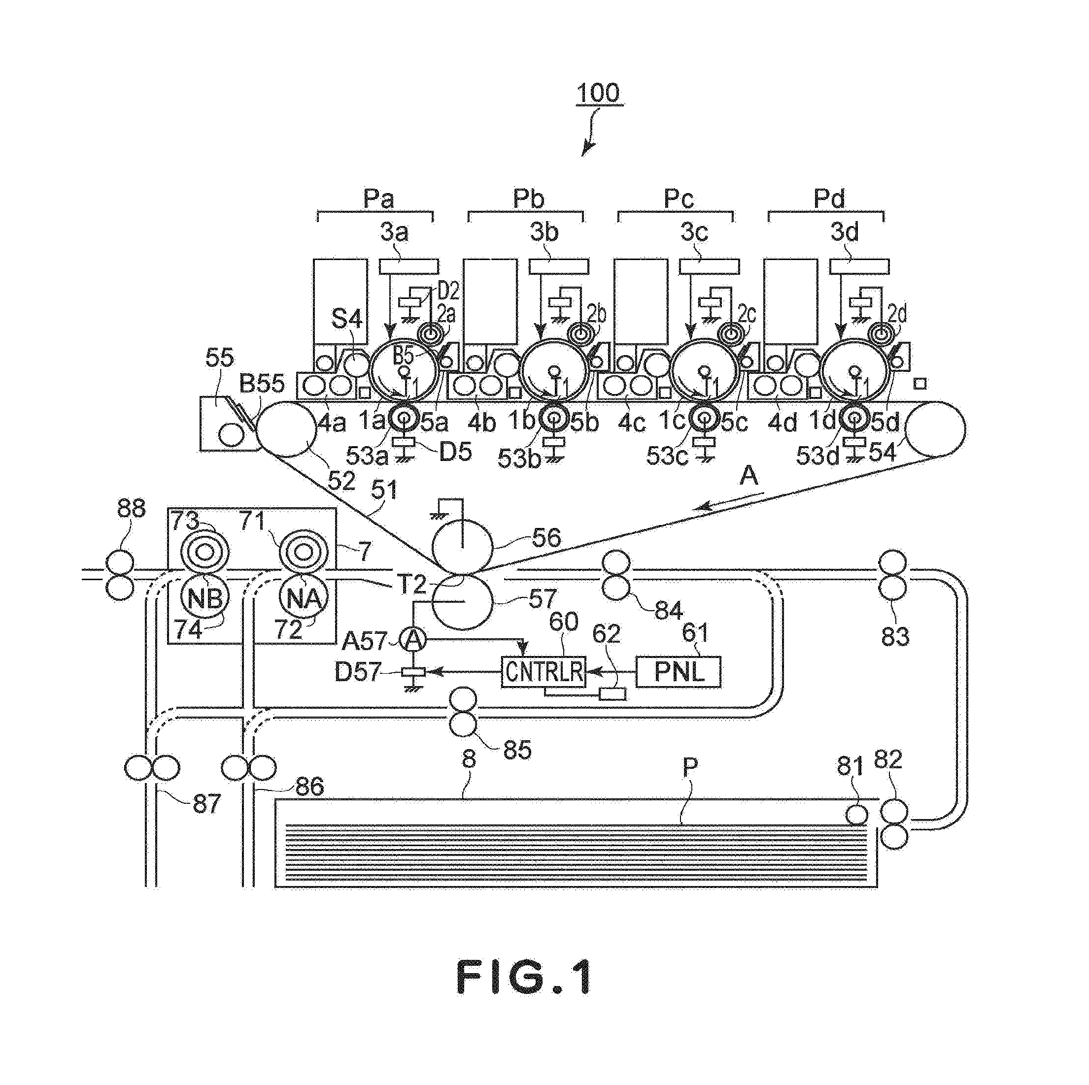
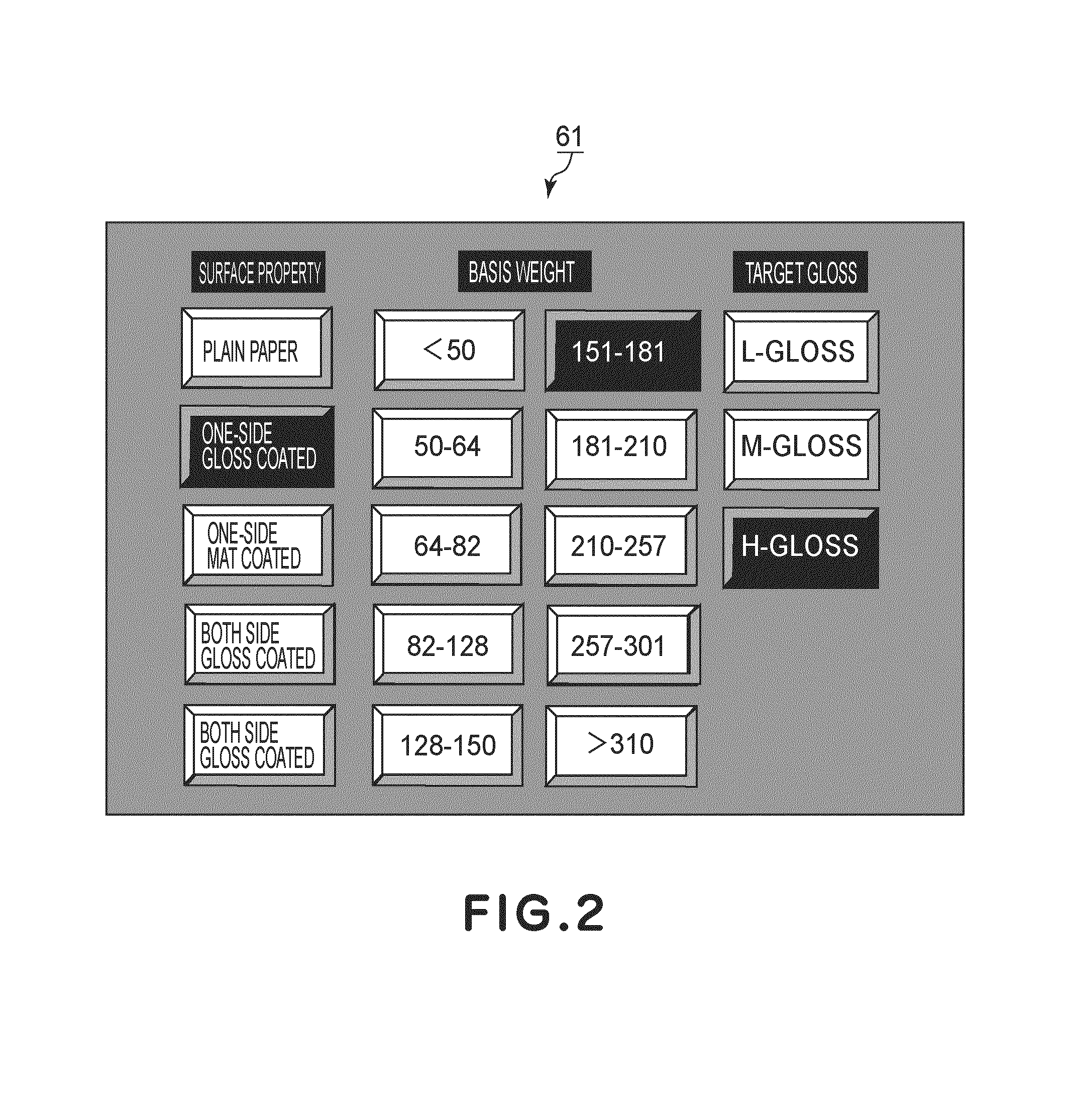
[0021]FIG. 1 is an illustration of an image forming apparatus of a first embodiment, FIG. 2 is an illustration of an operation panel for setting a fixing condition, and FIG. 3 is an illustration of a fixing device.

[0022]As shown in FIG. 1, the image forming apparatus 100 comprises voltage adjustment means (60) for adjusting the transfer voltage at the time of transferring the toner image onto a resupplied recording material P in response to the number of the heating portions (NA, NB) through which the recording material P has passed. The voltage adjustment means (60) adjusts transfer voltage in response to the kind of recording material P used (Table 2).

[0023]Image forming stations for magenta, cyan, yellow, and black colors Pa, Pb, Pc, Pd are arranged in a straight line section of an intermediary transfer belt 51, in series in the image forming apparatus 100. The intermediary transfer belt 51 is stretched around a driving roller 52, a tension roller 54, and an internal secondary tr...

second embodiment

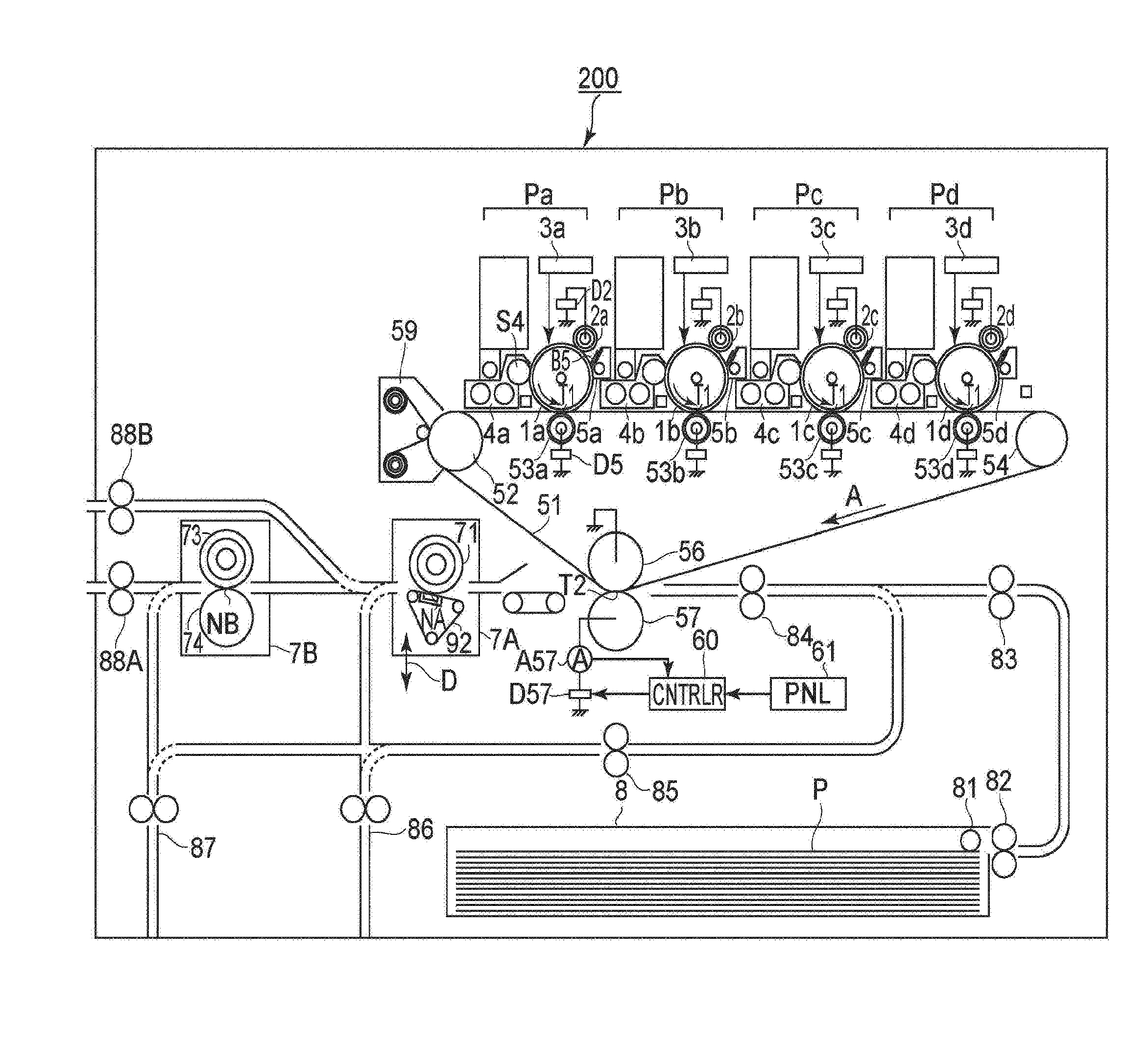
[0078]FIG. 5 is an illustration of an image forming apparatus of a second embodiment, and FIG. 6 is an illustration of an upstream fixing device. The image forming apparatus 200 of the second embodiment is the same as that of the first embodiment except having replaced the fixing device 7 of FIG. 1 with two fixing devices 7A, 7B. In the description of this embodiment, the same reference numerals as in the foregoing Embodiment are assigned to the elements having the corresponding functions in this embodiment and the detailed description thereof is omitted for simplicity. In addition, in each table, the fixing device 7A means the upper fixing device (lower belt fixing device), and the fixing device 7A, 7B means the two fixing devices.

[0079]As shown in FIG. 5, the image forming apparatus 200 is provided with two fixing devices 7A, 7B which have the fixing nips maintained at the press-contact states. The downstream fixing device is retractable from the feeding path of the recording mate...

third embodiment

[0092]FIG. 7 is an illustration of a transfer voltage setting including a resistance measurement of a transfer portion, and FIG. 8 is an illustration of a transfer voltage set correspondingly to a required transfer current. The third embodiment is related with a setting method of a usable transfer voltage in the image forming apparatus 200 of the second embodiment. Referring to FIG. 5, as to the structure of the image forming apparatus 200, the description will be omitted.

[0093]As shown in FIG. 5, the controller 60 controls the transfer power source D57 in the state without the recording material P, and measures the volt-ampere characteristic of the secondary transfer portion T2. The controller 60 sets the transfer voltage for the resupplied recording material P in response to the combination of the fixing devices having been used for the fixing and the measured volt-ampere characteristic. The transfer voltage is applied to the series circuit constituted by the external secondary tr...


PUM


Abstract

An image forming apparatus includes an image bearing member for carrying a toner image, a transferer supplied with a voltage to transfer a toner image from the member onto a recording material in a transfer portion, heaters with different heating conditions for heating the image transferred onto the material, a refeeder for refeeding the material to the transfer portion to transfer the image onto the material having the image fixed by the heater, a selector for selecting the glossiness of the image after fixing, a device for determining the heater to heat the image from the heaters in accordance with the glossiness selected by the selector, and a device for changing the voltage for transferring the image onto the refed material in accordance with the heater having heated the image on the material prior to the material being refed by the refeeder.

Description

FIELD OF THE INVENTION AND RELATED ART[0001]The present invention relates to an image forming apparatus in which a toner image is fixed by passing a recording material having a transferred toner image through a plurality of heating portions. Particularly, it is related with a control of a transfer voltage in the case that a toner image is retransferred to the recording material which already has the fixed toner image in a back side printing and so on.[0002]In a widely used image forming apparatus, a toner image carried on an image bearing members, such as a photosensitive drum, an intermediary transfer member, and so on, is transferred onto a recording material by a transfer portion which has the transferring means supplied with a transfer voltage, and thereafter, the recording material is passed through a heating portion, by which the toner image is fixed.[0003]JP 2000-221821-A discloses an image forming apparatus which has a plurality of heaters arranged in series with respect to ...

Claims


Application Information

Patent Timeline
Patent Type & Authority Patents(United States)
IPC IPC(8): G03G15/16G03G15/00G03G15/20
CPCG03G15/235G03G15/205G03G2215/00805G03G2215/1614G03G2215/2006G03G2215/0129
Inventor TOMIZAWA, TAKESHI
Owner CANON KK
Why Eureka
Try Eureka