
Ink jet image forming method and ink jet image forming apparatus

a technology of ink jet and image forming apparatus, which is applied in the direction of printing, duplicating/marking methods, inks, etc., can solve the problems of odor generation, curling or cockling, and difficulty in obtaining an image with a flat surfa

Active Publication Date: 2021-01-05
CANON KK
View PDF31 Cites 0 Cited by
  • Summary
  • Abstract
  • Description
  • Claims
  • Application Information

AI Technical Summary

Benefits of technology

The method enables satisfactory transfer of intermediate images to the recording medium while reducing the shift to the liquid absorbing member, thereby improving image flatness and preventing curling or cockling, by controlling the complex elastic modulus of the intermediate images within specific ranges.

Problems solved by technology

However, in many ultraviolet curable inks (hereinafter referred to as UV curable inks), all the ink components are cured by irradiation with ultraviolet rays, so a height of an image surface (thickness of an image) varies depending on the application amount of the ink, and therefore it is difficult to obtain an image with a flat surface.
However, the component that has a low viscosity and is cured by irradiation with ultraviolet rays has volatility, and there are problems such as the generation of odor, the environmental impact, or the like.
However, as a general property of the water-based ink, there is a case where a recording medium absorbs moisture in the ink to cause curling or cockling.
However, in the method described in Japanese Patent No. 4714949, since the water-based UV curable ink is directly applied to the recording medium, the penetration of the liquid components into the recording medium is unavoidable, and therefore curling and cockling are still likely to occur.
Further, it is found that when the liquid absorbing member described in Japanese Patent No. 4714949 is simply applied to a transfer type image forming apparatus such as Japanese Patent No. 5008645 and Japanese Patent Application Laid-Open No. 2012-86499, it is difficult to achieve the contradictory properties of satisfactorily transferring the intermediate image on the transfer body to the recording medium well without shifting the intermediate image to the liquid absorbing member.

Method used


Image

  • Ink jet image forming method and ink jet image forming apparatus
  • Ink jet image forming method and ink jet image forming apparatus
  • Ink jet image forming method and ink jet image forming apparatus

Examples


examples

[0210]The present invention will be described in detail below with reference to examples and comparative examples. The present invention is not limited to the following examples as long as the present invention does not depart from the gist. Unless otherwise specified, “part” represents parts by mass and “%” represents % by mass.

(Preparation of Pigment Dispersion)

[0211]After mixing the following raw materials, the obtained mixture was put into a batch type vertical sand mill (manufactured by AIMEX CO., LTD.), charged with 200 parts of zirconia bead having a diameter of 0.3 mm, water-cooled, and subjected to the dispersion treatment for 5 hours.[0212]Pigment red 122: 10%[0213]Resin aqueous solution (pigment dispersant): 15%

Resin: Styrene-acrylic acid-ethyl acrylate copolymer

(Acid value 150, weight average molecular weight 8000, aqueous solution of solid content of 20%, neutralizing agent KOH)[0214]Ion exchange water: 75%

[0215]Next, coarse particles of this dispersion were removed by ...

examples 1 to 20

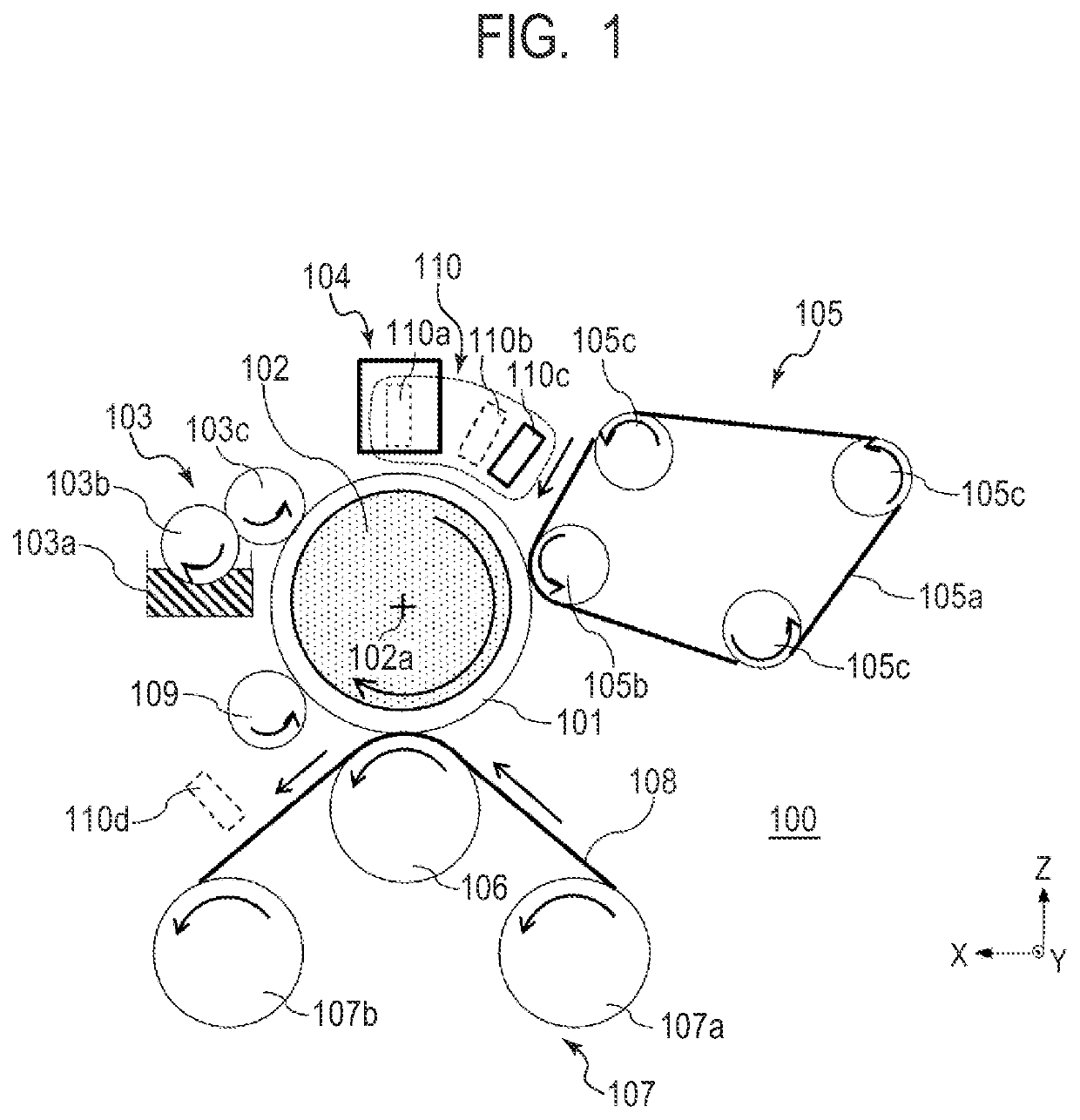
[0235]In these examples, image formation was performed using the following transfer type ink jet recording apparatus. A transfer body having the following configuration was used, and was fixed to a support member with an adhesive and then conveyed at a conveying speed of 600 mm / s. The transfer type ink jet recording apparatus does not particularly have a heating and cooling mechanism.

(Transfer Body)

[0236]A PET sheet having a thickness of 0.5 mm was coated with silicone rubber (trade name “KE12” manufactured by Shin-Etsu Chemical Co., Ltd.) to a thickness of 0.3 mm to form an elastic layer. Glycidoxypropyltriethoxysilane and methyltriethoxysilane were mixed at a molar ratio of 1:1 to produce a mixture of a condensate obtained by heating under reflux and a photocationic polymerization initiator (trade name “OPTOMER SP150” manufactured by ADEKA CORPORATION). Atmospheric pressure plasma treatment was performed so that the contact angle of water on the elastic layer surface was 10° or le...

examples 21 to 24

[0251]The ink to be applied was changed as shown in Table 4, and the reaction liquid was not applied. Except for this, the image formation and the measurement of complex elastic modulus were performed in the same manner as in Examples 1 to 20.

[0252]All the complex elastic moduli of the second intermediate images (before contacting the liquid absorbing member) were 4.0 or more in the common logarithm. Further, all the complex elastic moduli of the third intermediate image (before contacting the recording medium) were 7.0 or less.

[0253]

TABLE 4log10(G*(Pa))BeforecontactingBeforeliquidcontactingReactionabsorbingrecordingInkliquidmembermediumExample 11Presence4.13.8Example 224.64.1Example 335.45Example 4465.8Example 556.86.3Example 667.26.5Example 774.75Example 885.65.4Example 996.45.8Example 10106.96.5Example 11115.65.4Example 12126.15.8Example 13135.35.5Example 14145.25.4Example 15155.85.6Example 16166.76.3Example 17175.14.9Example 181854.8Example 19195.76Example 20204.24.5Example 211A...


PUM


Abstract

Provided are an ink jet image forming method and an ink jet image forming apparatus in which a complex elastic modulus (Pa) before an intermediate image comes into contact with a liquid absorbing member is 4.0 or more in the common logarithm, and a complex elastic modulus (Pa) before the intermediate image comes into contact with the recording medium is 7.0 or less in the common logarithm.

Description

CROSS-REFERENCE TO RELATED APPLICATIONS[0001]This application is a Continuation of International Patent Application No. PCT / JP2018 / 024714, filed Jun. 28, 2018, which claims the benefit of Japanese Patent Applications No. 2017-129728, filed Jun. 30, 2017, and No. 2017-129729, filed Jun. 30, 2017, all of which are hereby incorporated by reference herein in their entirety.BACKGROUND OF THE INVENTIONField of the Invention[0002]The present invention relates to an ink jet image forming method and an ink jet image forming apparatus.Description of the Related Art[0003]In a liquid image forming apparatus typified by an ink jet recording apparatus, a recording apparatus using an ink that is cured with active energy rays has been proposed and put into practical use. In general, the active energy rays used for curing are often ultraviolet rays. Since the ink undergoes a polymerization reaction by irradiation with ultraviolet rays to become a cured product, there is an advantage that a printed m...

Claims


Application Information

Patent Timeline
Patent Type & Authority Patents(United States)
IPC IPC(8): B41J2/005B41J11/00B41J2/01
CPCB41J11/002B41J2/0057B41J2/01B41J2002/012B41M5/0017B41M5/0256B41M5/03B41M7/00B41M7/0081B41J11/00214B41M5/0023C09D11/101C09D11/104
Inventor ORIHARA, TATSUAKISHINJO, KENJI
Owner CANON KK
Learn More