Multi-fluid jetting device

Inactive Publication Date: 2005-07-19
FUNAI ELECTRIC CO LTD
View PDF17 Cites 0 Cited by
  • Summary
  • Abstract
  • Description
  • Claims
  • Application Information

AI Technical Summary

Problems solved by technology

One of the challenges facing the manufacture and use of such miniature jetting devices is providing a device that is capable of dispensing two or more fluids at a time to provide a desired result.
Another challenge

Method used


Image

  • Multi-fluid jetting device
  • Multi-fluid jetting device
  • Multi-fluid jetting device

Examples


Embodiment Construction

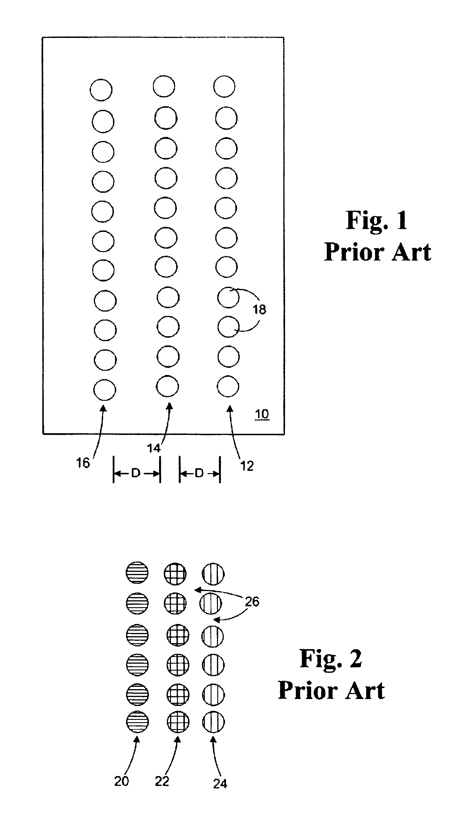
[0023]With reference to FIG. 1, a prior art multi-fluid nozzle plate 10 for a jetting device is shown. The nozzle plate 10 includes three columns 12, 14, and 16 containing a plurality of nozzles 18 in each column. Nozzle column 14 is displaced from nozzle columns 12 and 16 by distance D. Each column 12, 14, and 16 is dedicated to depositing a different color ink or different fluid on a print media. It will be appreciated that deposition of two or more dots of fluids other than inks is possible with such fluid jetting devices. However, for ease of describing the invention, the discussion will be focused on the deposition of ink.

[0024]In FIG. 2, ink dots 20 represent blue color dots, ink dots 22 represent yellow color dots, and ink dots 24 represent magenta color dots. Dots 20, 22, and 24 deposited from the nozzle plate 10 attached to a jetting device at substantially the same time will also have a significant amount of white space 26 between adjacent dots as deposited, for example, o...


PUM


Abstract

An improved multi-fluid jetting device. The jetting device includes a nozzle plate having a substantially planar surface for ejecting a fluid therefrom. The nozzle plate has at least 10 or more nozzles wherein groups of three adjacent nozzles are arranged in a triad orientation and wherein at least two adjacent nozzles in said triad orientation are coupled to two different fluid sources for fluid ejection from said adjacent nozzles substantially perpendicular to said nozzle plate surface.

Description

FIELD OF THE INVENTION[0001]The invention relates to improved multi-fluid jetting devices for dispensing a variety of fluids, preferably for dispensing two or more different fluids for a variety of applications.BACKGROUND OF THE INVENTION[0002]Micro-miniature fluid jetting devices are suitable for a wide variety of applications including hand-held ink jet printers, ink jet highlighters, ink jet air brushes, miniature evaporative coolers, and delivery of controlled quantities of medicinal fluids and purified water to precise locations. One of the challenges facing the manufacture and use of such miniature jetting devices is providing a device that is capable of dispensing two or more fluids at a time to provide a desired result. Such a process is particularly useful for providing color images, however, the process is not limited to ink jet printing applications.[0003]Another challenge facing the manufacture and use of such devices is the provision of a device capable of dispensing mu...

Claims


Application Information

Patent Timeline
IPC IPC(8): B41J2/21
CPCB41J2/211B41J3/36
Inventor AHNE, ADAM J.ANDERSON, FRANK E.ZBROZEK, JOHN D.
Owner FUNAI ELECTRIC CO LTD
Why Eureka
Try Eureka