Transfer apparatus and transfer method

a transfer apparatus and transfer method technology, applied in the field of transfer techniques, can solve the problems of not being able to satisfactorily transfer an object, and the difficulty of transferring an object is similar to the problem of not being able to achieve the effect of satisfactorily transfer

Active Publication Date: 2019-09-17
DAINIPPON SCREEN MTG CO LTD
View PDF4 Cites 0 Cited by
  • Summary
  • Abstract
  • Description
  • Claims
  • Application Information

AI Technical Summary

Benefits of technology

[0009]According to a second aspect of the disclosure, there is provided a transfer method that brings one principal surface of a first plate-like body and one principal surface of a second plate-like body into contact and transferring an object to be transferred carried on one of the first and second plate-like bodies to the other. The method comprises: a supporting step of supporting the one principal surface of the first plate-like body and the one principal surface of the second plate-like body proximately facing each other across the object to be transferred; and a transferring step of rolling a roller member including a rotary shaft parallel to the other principal surface of the second plate-like body with respect to the second plate-like body in a traveling direction perpendicular to the rotary shaft and parallel to the other principal surface of the second plate-like body to transfer the object to be transferred while biasing the roller member in a pressing direction from the second plate-like body toward the first plate-like body and pressing the second plate-like body against the first plate-like body; wherein the transferring step includes a step of changing a force for biasing the roller member according to a contact state of the first and second plate-like bodies during travel of the roller member and suppressing a variation of a pressing force per unit area given from the second plate-like body to the first plate-like body during the travel.
[0011]As described above, according to the invention, a variation of the pressing force per unit area given to the first plate-like body can be suppressed by controlling the biasing force of the roller member to the second plate-like body during the travel of the roller member, i.e. the object to be transferred can be satisfactorily transferred by stabilizing the above pressing force.

Problems solved by technology

Thus, it is difficult to satisfactorily transfer an object to be transferred to a semiconductor wafer by the apparatus described in JP2014-184716A.
Such a problem similarly occurs not only when the contact area varies, but also when the contact state varies due to other factors.

Method used


Image

  • Transfer apparatus and transfer method
  • Transfer apparatus and transfer method
  • Transfer apparatus and transfer method

Examples


first embodiment

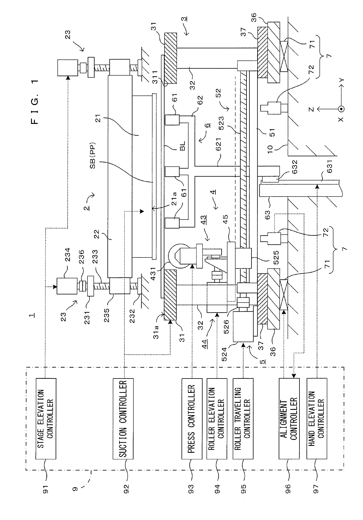
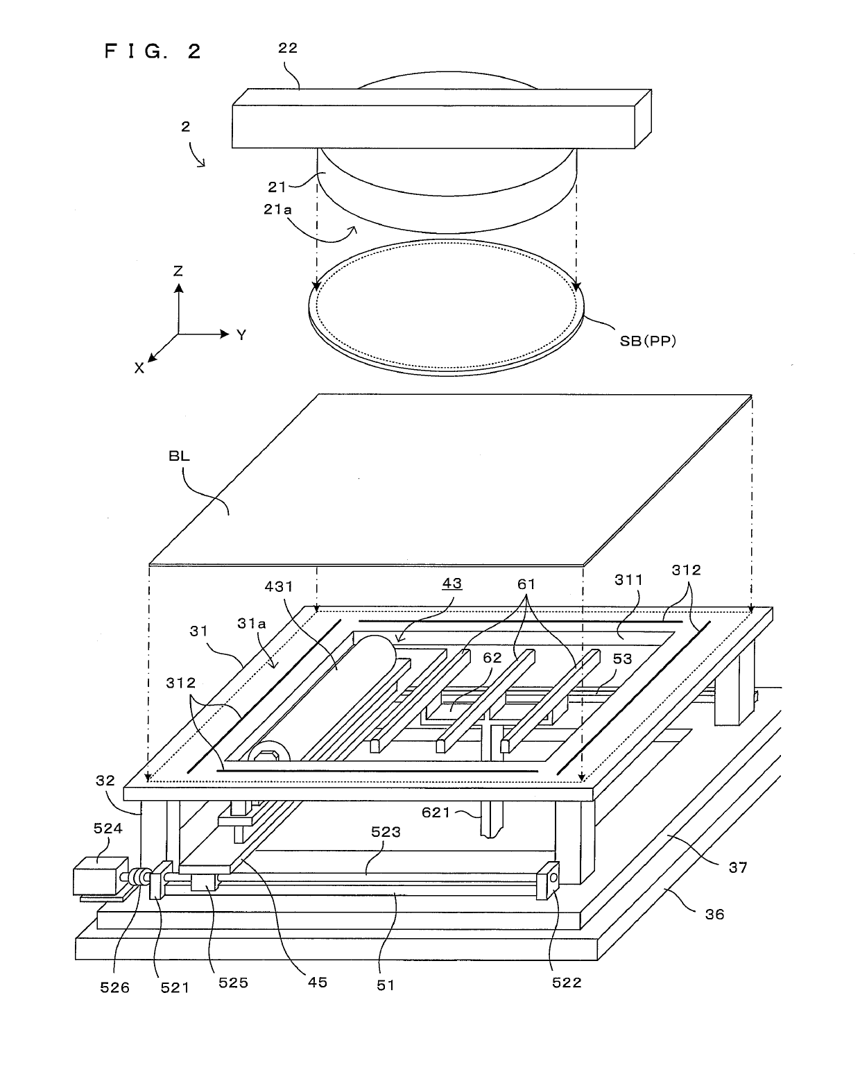
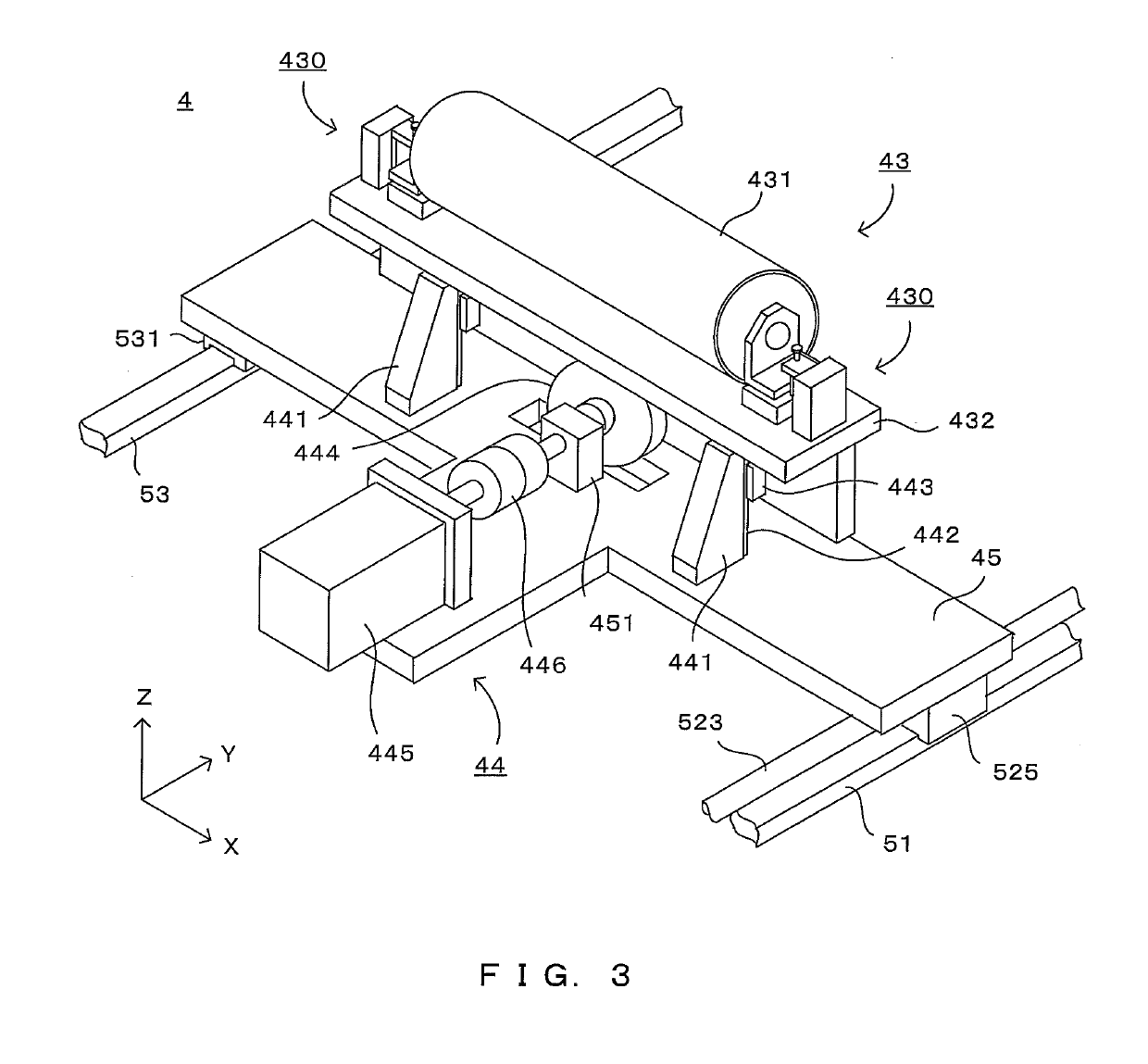
[0026]FIG. 1 is a side view schematically showing a transfer apparatus according to this invention. Further, FIG. 2 is a diagram showing the configuration of a main part of this transfer apparatus. XYZ orthogonal coordinate axes are set as shown in FIG. 1 to comprehensively show directions in each figure. Here, an XY plane represents a horizontal plane. Further, a Z axis represents a vertical axis, more specifically, a (−Z) direction represents a vertically downward direction.

[0027]This transfer apparatus 1 is structured such that an upper stage block 2, a lower stage block 3, a transfer roller block 4, a roller travel driver 5, a supporting hand unit 6 and an alignment unit 7 are arranged on a main frame 10. Further, besides the above, the transfer apparatus 1 includes a control unit 9 for performing a predetermined operation by controlling each component of the apparatus in accordance with a processing program stored in advance.

[0028]First, the overall configuration of the transfe...

second embodiment

[0077]In the second embodiment, a contact area where the substrate SB or the like and a blanket BL are in contact by pressing by the transfer roller 431 is constant regardless of the position of the transfer roller 431. Thus, the biasing forces need not be controlled according to the contact area. However, since the blanket BL is sucked and held by suction grooves 312, bending rigidity of the blanket BL is relatively high when the transfer roller 431 is located at a transfer start position or a transfer end position if distances between the suction grooves 312 and the transfer start position and the transfer end position are short as shown in FIG. 11. Here, “bending rigidity” means the rigidity of the blanket BL against a pressing force generated by the biasing of the transfer roller 431, i.e. difficulty to deform, the bending rigidity suddenly increases as the above distances become shorter, and a profile as shown in a graph (b) in FIG. 11 is developed in the transfer apparatus 1. ...

third embodiment

[0083]Further, the contact state may change depending on a pattern as an object to be transferred. For example, a transfer amount of a pattern forming material may vary depending on the type of the pattern and it is desirable to set suitable biasing forces according to that variation. For example, as shown in FIG. 12, pattern elements PT1 to PT3 having mutually different transfer amounts may be included. Here, the transfer amount of the pattern elements PT1 is largest, and the transfer amount becomes smaller in the order of the pattern elements PT2 and PT3. Thus, if the transfer roller 431 is biased with constant biasing forces, the pressing force per unit area may change according to the Y-direction position of the transfer roller 431. For example, in an area where the transfer amount is large such as the pattern element PT1, the pressing force per unit area is insufficient and a sufficient transfer is not performed. Conversely, in an area where the transfer amount is small such as...


PUM


Abstract

Force for biasing a roller member is changed according to the contact state of first and second plate-like bodies during the travel of the roller member. By that, the pressing force per unit area given from the second plate-like body to the first plate-like body during travel is suppressed. An object to be transferred is satisfactorily transferred despite a change in the contact state of the plate-like bodies during the travel of the roller member.

Description

CROSS REFERENCE TO RELATED APPLICATION[0001]The disclosure of Japanese Patent Application No. 2016-146218 filed on Jul. 26, 2016 including specification, drawings and claims is incorporated herein by reference in its entirety.BACKGROUND OF THE INVENTION[0002]1. Field of the Invention[0003]This invention relates to a transfer technique for transferring an object to be transferred from one plate body to another plate body by bringing two plate bodies into contact.[0004]2. Description of the Related Art[0005]A technique for transferring an object to be transferred such as a pattern or thin film carried on a principal surface of one plate-like body to another plate-like body by bringing two plate-like bodies into contact with each other is known as a technique for forming a pattern or thin film on a plate-like body such as a glass substrate or semiconductor substrate. One method of this is to bring two plate-like bodies into contact and transfer an object to be transferred by biasing a ...

Claims


Application Information

Patent Timeline
Patent Type & Authority Patents(United States)
IPC IPC(8): B41F16/00H01L21/67H01L21/683B41M1/10B44C1/10
CPCB41F16/0033B44C1/10H01L21/67092H01L21/6838B41F16/002H01L21/67132B41M1/10B41F16/00
Inventor KAJINO, ITSUKIMASUICHI, MIKIOUENO, HIROYUKISHOJI, KAZUHIRO
Owner DAINIPPON SCREEN MTG CO LTD
Why Eureka
Try Eureka