High integrity perception program

a high integrity, perception technology, applied in the direction of electric programme control, program control, instruments, etc., can solve the problems of unreliable unmanned equipment, equipment completely different from operator-controlled equipment, and inability to allow

Active Publication Date: 2013-07-02
DEERE & CO
View PDF134 Cites 40 Cited by
  • Summary
  • Abstract
  • Description
  • Claims
  • Application Information

AI Technical Summary

Problems solved by technology

In some situations with the trend, this equipment is completely different from the operator-controlled equipment that is being replaced, and does not allow for any situations in which an operator can be present or take over operation of the vehicle.
Such unmanned equipment can be unreliable due to the complexity of systems involved, the current status of computerized control, and uncertainty in various operating environments.

Method used


Image

  • High integrity perception program
  • High integrity perception program
  • High integrity perception program

Examples


Embodiment Construction

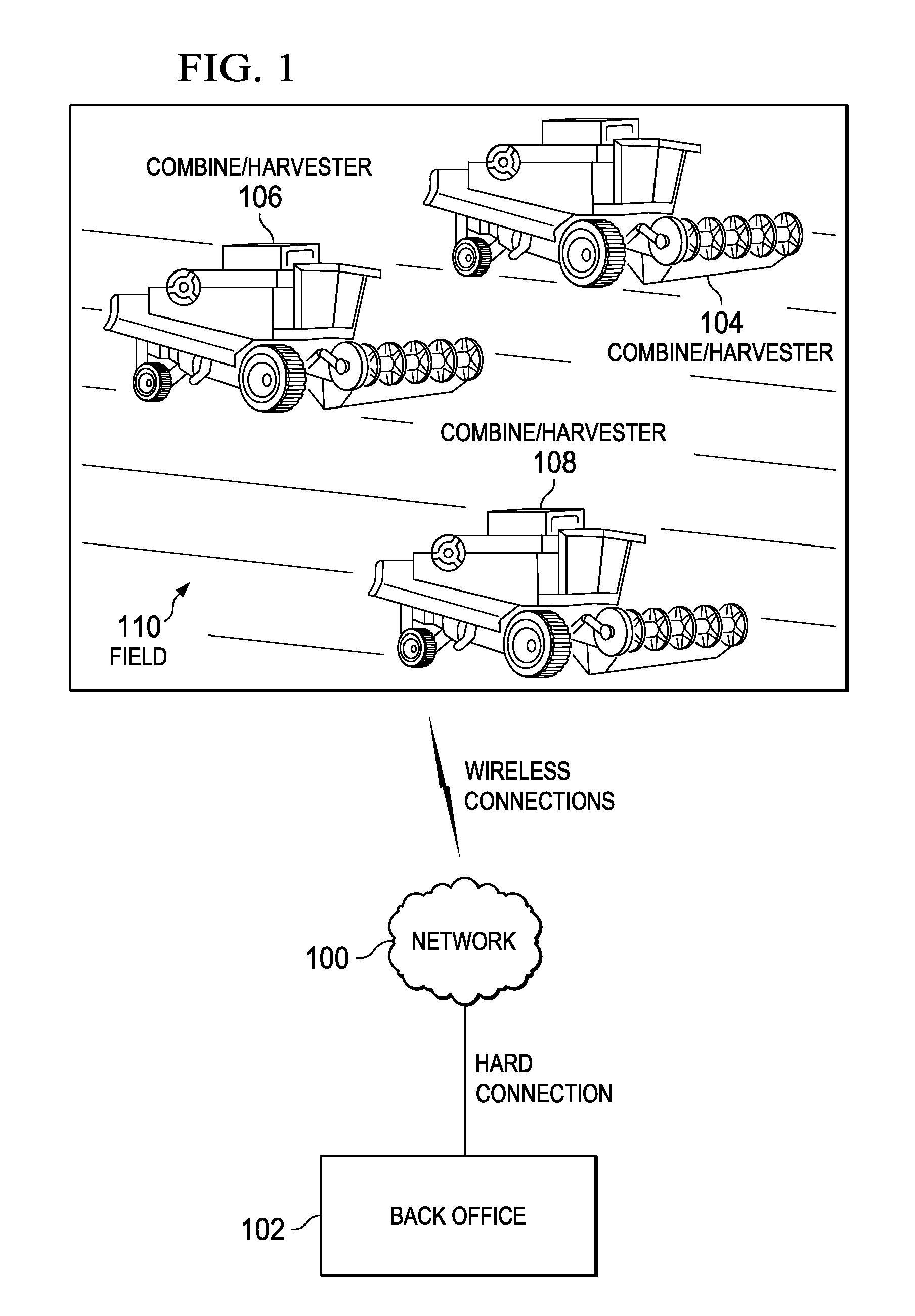
[0025]Embodiments of this invention provide systems and methods for vehicle navigation and more particularly systems and methods for a distributed knowledge base within a vehicle for controlling operation of a vehicle. As an example, embodiments of this invention provide a method and system for utilizing a versatile robotic control module for localization and navigation of a vehicle.

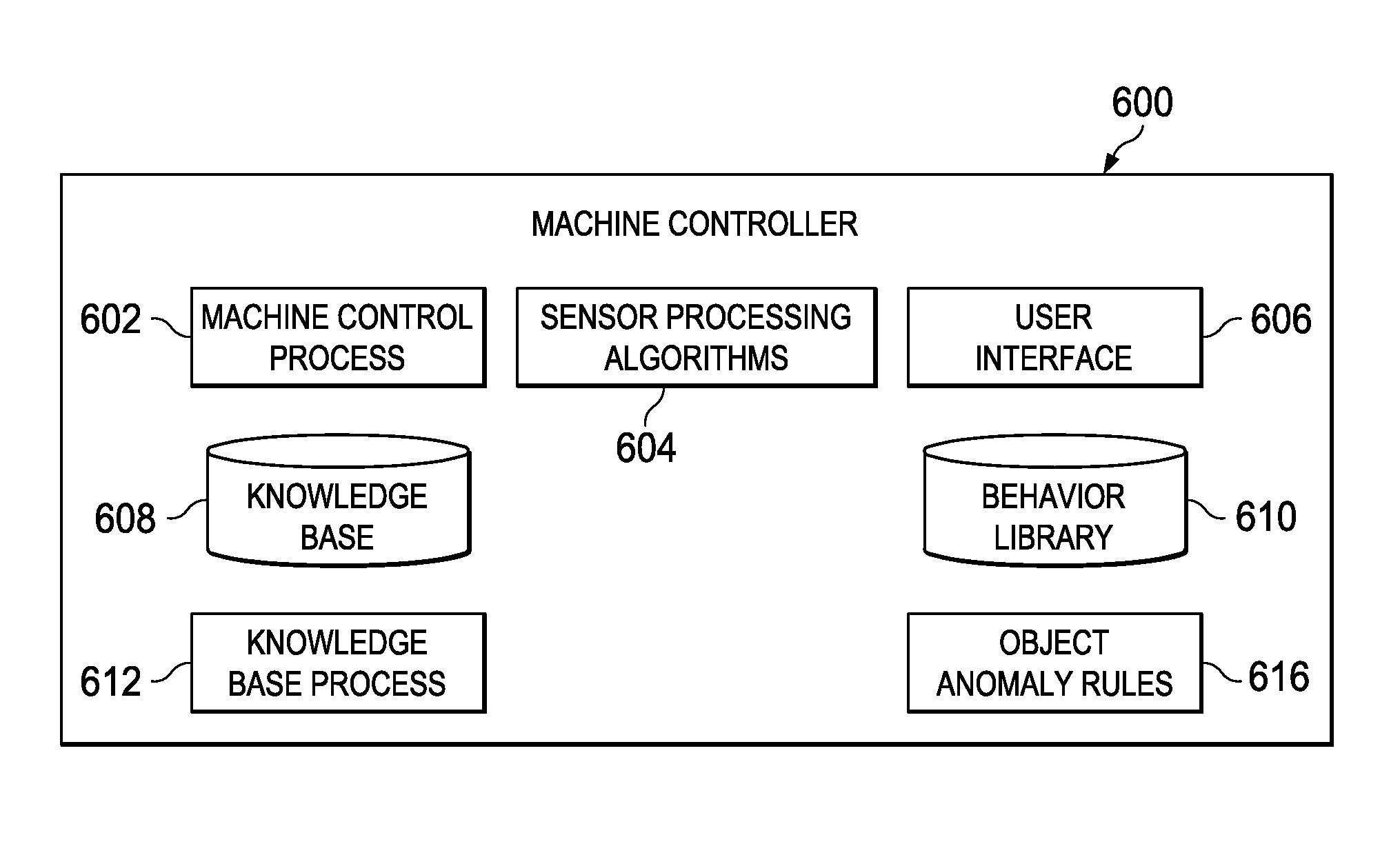
[0026]Robotic or autonomous vehicles, sometimes referred to as mobile robotic platforms, generally have a robotic control system that controls the operational systems of the vehicle. In a vehicle that is limited to a transportation function, the operational systems may include steering, braking, transmission, and throttle systems. Such autonomous vehicles generally have a centralized robotic control system for control of the operational systems of the vehicle. Some military vehicles have been adapted for autonomous operation. In the United States, some tanks, personnel carriers, Stryker vehicles, and oth...


PUM


Abstract

The illustrative embodiments provide a computer program product for processing sensor data and controlling the movement of a vehicle. In an illustrative embodiment, an operating environment around the vehicle is identified and sensor data is selected from a set of sensors. A dynamic condition is identified using a plurality of different types of sensors on the vehicle. In response to the dynamic condition being identified, the movement of the vehicle is controlled. In another illustrative embodiment, an environment around the vehicle is identified to form an operating environment. Sensor data is selected from a set of sensors in a plurality of redundant sensors based on the operating environment.

Description

CROSS REFERENCE TO RELATED APPLICATIONS[0001]This application is related to commonly assigned U.S. patent application Ser. No. 12 / 208,752 entitled “Leader-Follower Semi-Autonomous Vehicle with Operator on Side”; U.S. patent application Ser. No. 12 / 208,659 entitled “Leader-Follower Fully-Autonomous Vehicle with Operator on Side”, which is now U.S. Pat. No. 8,229,618; U.S. patent application Ser. No. 12 / 208,691 entitled “High Integrity Perception for Machine Localization and Safeguarding”; U.S. patent application Ser. No. 12 / 208,666 entitled “Distributed Knowledge Base For Vehicular Localization And Work-Site Management”, which is now U.S. Pat. No. 8,195,342; U.S. patent application Ser. No. 12 / 208,782 entitled “Distributed Knowledge Base Method For Vehicular Localization And Work-Site Management”; U.S. patent application Ser. No. 12 / 208,721 entitled “Distributed Knowledge Base Program For Vehicular Localization and Work-Site Management”, which is now U.S. Pat. No. 8,224,500; U.S. pat...

Claims


Application Information

Patent Timeline
Patent Type & Authority Patents(United States)
IPC IPC(8): G05D1/00
CPCG05D1/024G05D1/0272G05D1/0242G05D1/0255G05D1/0257G05D1/0274G05D1/0278G05D1/028
Inventor ANDERSON, NOEL WAYNE
Owner DEERE & CO
Why Eureka
Try Eureka