System stabilizing device

a system stabilizing device and system technology, applied in the direction of instrumentation, process and machine control, material dimension control, etc., can solve the problems of slow response of governor control, general environmental influence of power generation utilizing natural energy such as sunlight or wind power, fluctuation of power generation amount, etc., to achieve optimal system stabilizing control

Inactive Publication Date: 2013-07-09
MEIDENSHA ELECTRIC MFG CO LTD
View PDF7 Cites 2 Cited by
  • Summary
  • Abstract
  • Description
  • Claims
  • Application Information

AI Technical Summary

Benefits of technology

[0157]According to the present invention, the system stabilizing device does not misconceive that the frequency fluctuation due to the governor control of the generator or the voltage amplitude fluctuation due to AVR (automatic voltage regulating) control of the generator has been caused by a load fluctuation. Thus, the system stabilizing device can exercise optimal system stabilizing control, without interfering with the governor control or AVR control.

Problems solved by technology

Power generation utilizing natural energy such as sunlight or wind power is generally susceptible to environmental influence, and the amount of power generation fluctuates greatly.
However, governor control is slow in response.
Thus, if electric power consumed by the load 12 suddenly changes, the internal combustion engine type power generation equipment cannot follow such a sudden change (sudden excess or deficiency) in electric power.
When the power load sharply increases at this time, the torque of the generator becomes insufficient for the load power, so that the number of revolutions decreases to lower the frequency of the voltage.
However, governor control is slow in response, so that if the load sharply increases, a decrease in the frequency lasting for several seconds or so occurs.
If such a plurality of governor controls interfere with each other, oscillations, etc. occur in the system voltage, rendering power supply from the dispersed generation plant 11 to the load 12 unstable.
However, AVR control is slow in response, so that if the load sharply increases, a decrease in the voltage lasting for several seconds or so occurs.

Method used


Image

  • System stabilizing device
  • System stabilizing device
  • System stabilizing device

Examples


embodiment 1

[0171

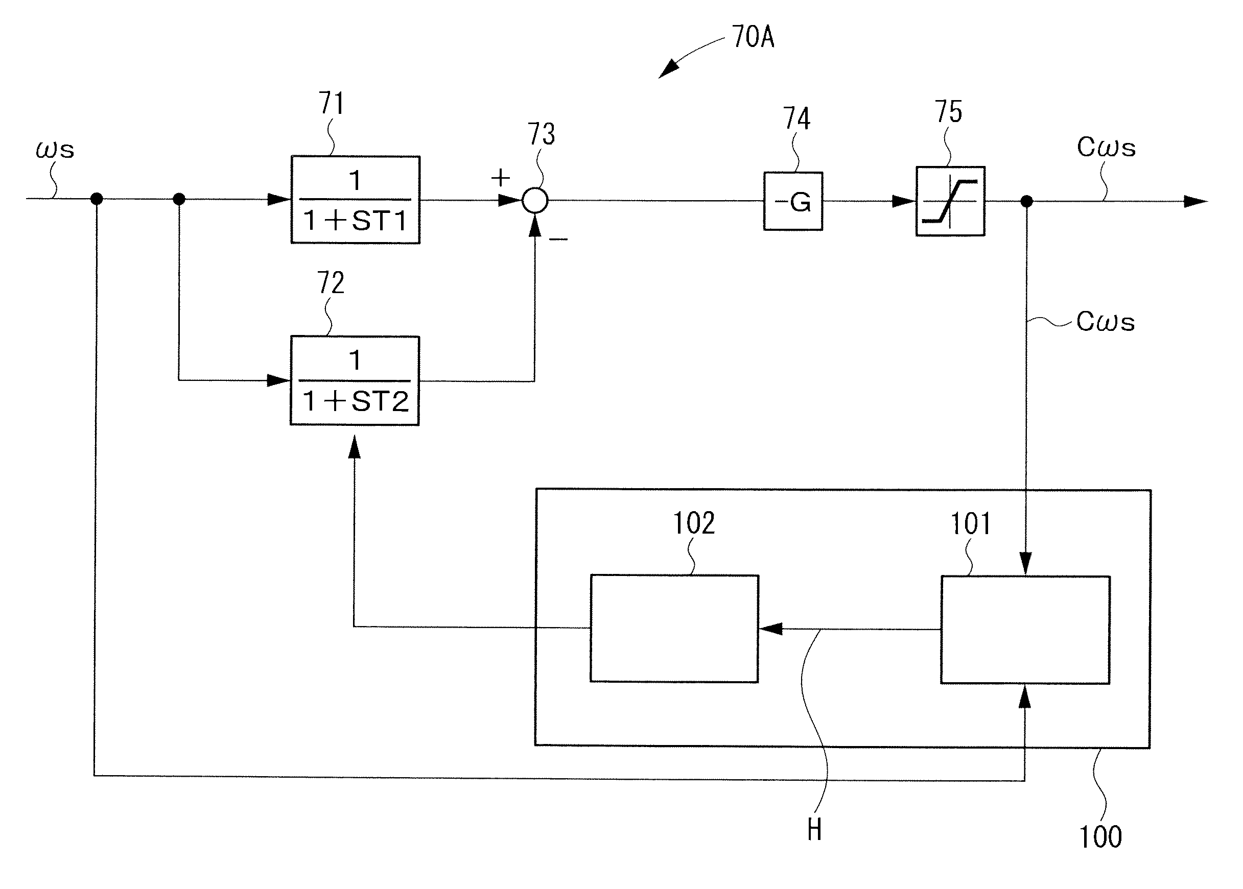
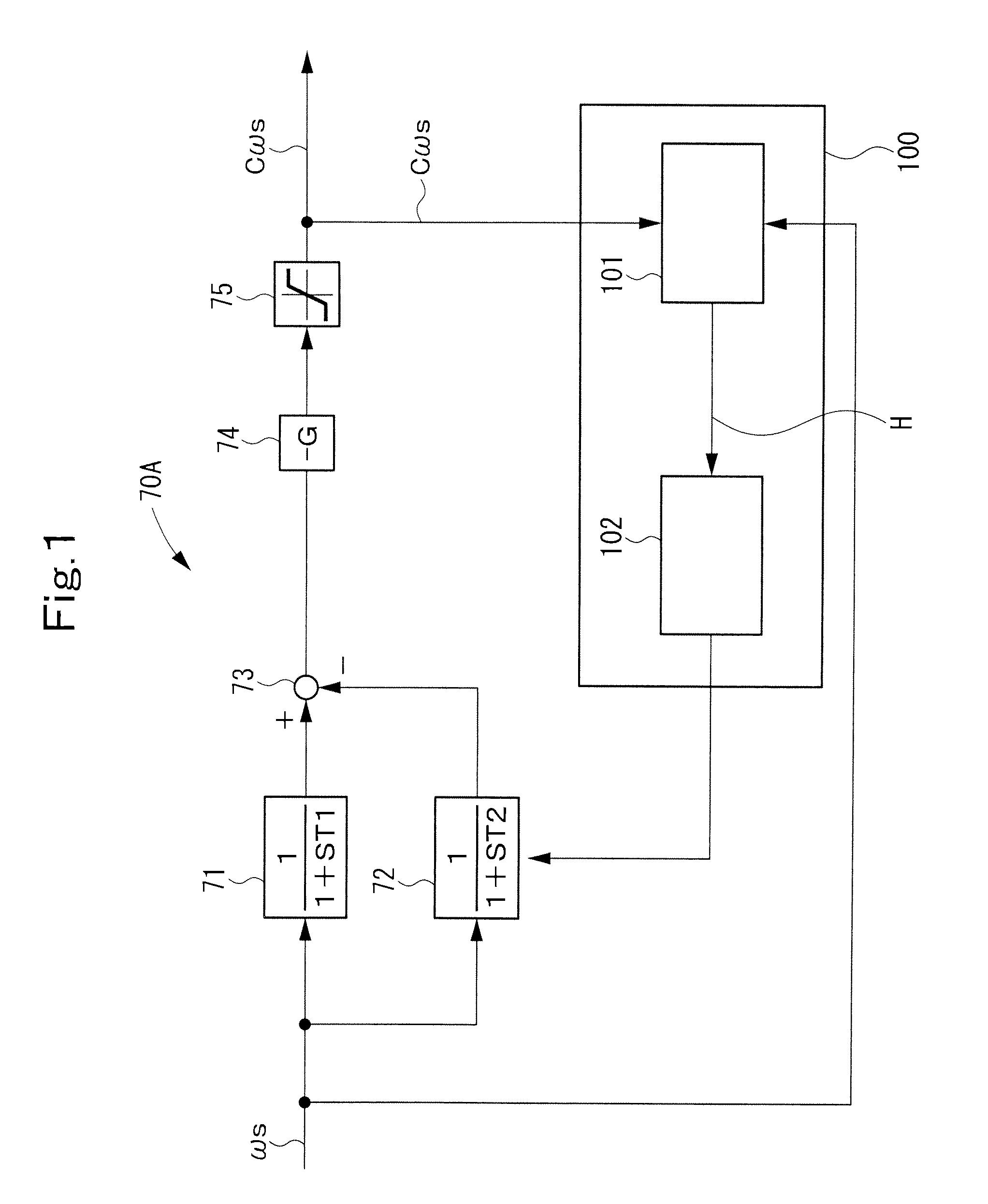
[0172]FIG. 1 shows a fluctuation detecting block 70A according to Embodiment 1 of the present invention. This fluctuation detecting block 70A has an interference action inhibiting unit 100 further added to the configuration of the fluctuation detecting block 70 shown in FIG. 9.

[0173]Thus, the interference action inhibiting unit 100 will be mainly described, with the same parts as those in the fluctuation detecting block 70 being assigned the same numerals as in the fluctuation detecting block 70, and a duplicate explanation being omitted.

[0174]In this embodiment, the fluctuation detecting block 70A is applied to the fluctuation detecting block 42 of the system stabilizing device 20 shown in FIG. 8, which is designed to output the fluctuation component Cωs as the optimal value, without interfering with the governor control of the generator.

[0175]The inference action inhibiting unit 100 has an interference action judgment block 101, and a time constant changing block 102.

[0176]Th...

embodiment 2

[0202

[0203]FIG. 3 shows a fluctuation detecting block 80A according to Embodiment 2 of the present invention. This fluctuation detecting block 80A has an interference action inhibiting unit 200 further added to the configuration of the fluctuation detecting block 80 shown in FIG. 10.

[0204]Thus, the interference action inhibiting unit 200 will be mainly described, with the same parts as those in the fluctuation detecting block 80 being assigned the same numerals as in the fluctuation detecting block 80, and a duplicate explanation being omitted.

[0205]In this embodiment, the fluctuation detecting block 80A is applied to the fluctuation detecting block 42 of the system stabilizing device 20 shown in FIG. 8, which is designed to output the fluctuation component Cωs as the optimal value, without interfering with the governor control of the generator.

[0206]The inference action inhibiting unit 200 has an interference action judgment block 201, and a cushioning time changing block 202.

[0207...

embodiment 3

[0232

[0233]FIG. 5 shows a fluctuation detecting block 80B according to Embodiment 3 of the present invention. This fluctuation detecting block 80B has the configuration of the fluctuation detecting block 80A shown in FIG. 3, but in which the actions and functions of the interference action judgment block 201 and the cushioning time changing block 202 have been modified.

[0234]The interference action judgment block 201 has a judgment block 201a, a multiplier 201b, an adder 201c, a limiter 201d, and a delay circuit 201e.

[0235]The judgment block 201a has the aforementioned judgment conditions (i) and (ii) set therein and, when either of the reaction conditions (i) and (ii) is fulfilled, outputs the cushioning time changing signal h.

[0236]Since the multiplier 201b, the adder 201c, the limiter 201d, and the delay circuit 201e perform an integrating function, the cushioning time changing signal h outputted from the interference action judgment block 201 increases with the passage of time....


PUM


Abstract

A self-contained control unit of a system stabilizing device installed on a microgrid is provided with a fluctuation detecting block 70A for determining a fluctuation component of the frequency of system voltage (Cωs) and a fluctuation component of voltage amplitude of the system voltage (C|Vs|). The fluctuation detecting block 70A determines the fluctuation component (Cωs) based on a deviation between the output signal of a low-pass filter 71 for noise removal and the output signal of a low-pass filter 72 for determining a fluctuation detection time. An interference action inhibiting unit 100 judges whether system stabilizing control and governor control of a generator interfere with each other, based on a frequency signal ωs and the fluctuation component Cωs. If there is interference, the time constant of the low-pass filter 72 is reduced to reduce the fluctuation component Cωs, thereby decreasing the amount of control by the system stabilizing device and preventing interference. By this measure, system stabilizing control is exercised, without interfering with the governor control or AVR control of the generator.

Description

TECHNICAL FIELD[0001]This invention relates to a system stabilizing device, which is designed to be capable of exercising optimal system stabilizing control during an isolated or self-supporting run, without interfering with generator governor control or AVR (automatic voltage regulating) control.BACKGROUND ART[0002]Power generation utilizing natural energy such as sunlight or wind power is generally susceptible to environmental influence, and the amount of power generation fluctuates greatly. A system stabilizing device is used for the purpose of accommodating or absorbing this fluctuation.[0003]In a microgrid having a network constructed by installing a power source, such as natural energy, near the electric power demand side, the installation of a system stabilizing device, which keeps demand for and supply of electric power in balance, is necessary for system stabilization.[0004]An example of the microgrid (electric distribution or distribution system) equipped with a system sta...

Claims


Application Information

Patent Timeline
Patent Type & Authority Patents(United States)
IPC IPC(8): G05D3/12G05D17/00G05D5/00G05D9/00G05D11/00
CPCH02J3/42Y02P80/14
Inventor OI, KAZUNOBUMUNESHIMA, MASAKAZUKIMURA, AKIHIRO
Owner MEIDENSHA ELECTRIC MFG CO LTD
Why Eureka
Try Eureka