Snap button

a button and button technology, applied in the field of snap buttons, can solve the problems of difficult button attaching work, and achieve the effect of easy passing, less force required, and more elastic or flexibl

Active Publication Date: 2013-07-16
YKK CORP
View PDF31 Cites 25 Cited by
  • Summary
  • Abstract
  • Description
  • Claims
  • Application Information

AI Technical Summary

Benefits of technology

[0013]In the present invention, the protrusion may have one or more cutouts. When the two snap buttons are engaged and disengaged, the salients of one of the snap buttons and the protrusions of the other come into contact with each other and elastically deformed, and then they are restored just after mutually passing over. The cutouts can make the protrusion more elastic or flexible, decreasing a force required for the engaging and disengaging actions between the two snap buttons. Besides, the cutouts may be slits and the like.
[0014]In the present invention, the salient may be hemispherically shaped. The hemispheric salient can more easily pass over the protrusion, decreasing a force required for the engaging and disengaging actions between the two snap buttons.
[0015]In the present invention, the circumferential range of each recess is larger than that of each projection, and therefore, when the projections of one of the two snap buttons are matched with the recesses of the other button, it is easy to position each projection with respect to each recess. Further, with the projection tapered off from the proximal end to the distal end, it is easier to position the projection with respect to the recess. Furthermore, with the one or more cutouts in the protrusion and the hemispheric salient, their slopes can serve as a guide to introduce the projection into the recess to match with, even if the axes of the two snap buttons are not aligned.

Problems solved by technology

In addition, when the two snap buttons are attached to cloths, they have to be fixed in proper and accurate circumferential positions, which makes the work of attaching buttons to cloths difficult.

Method used


Image

  • Snap button
  • Snap button
  • Snap button

Examples


Embodiment Construction

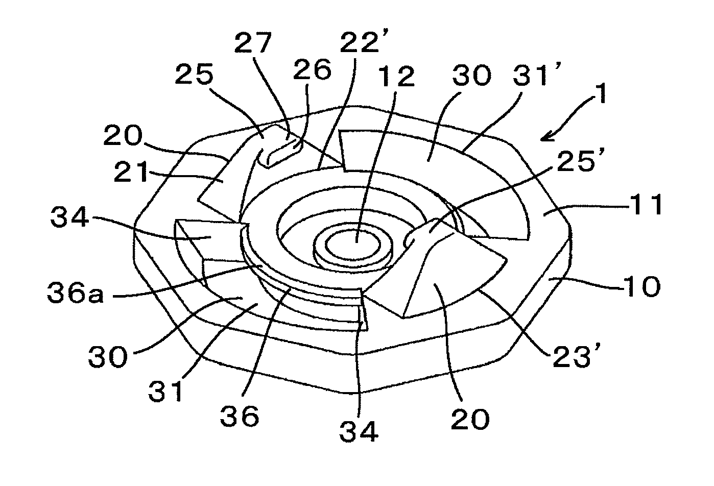
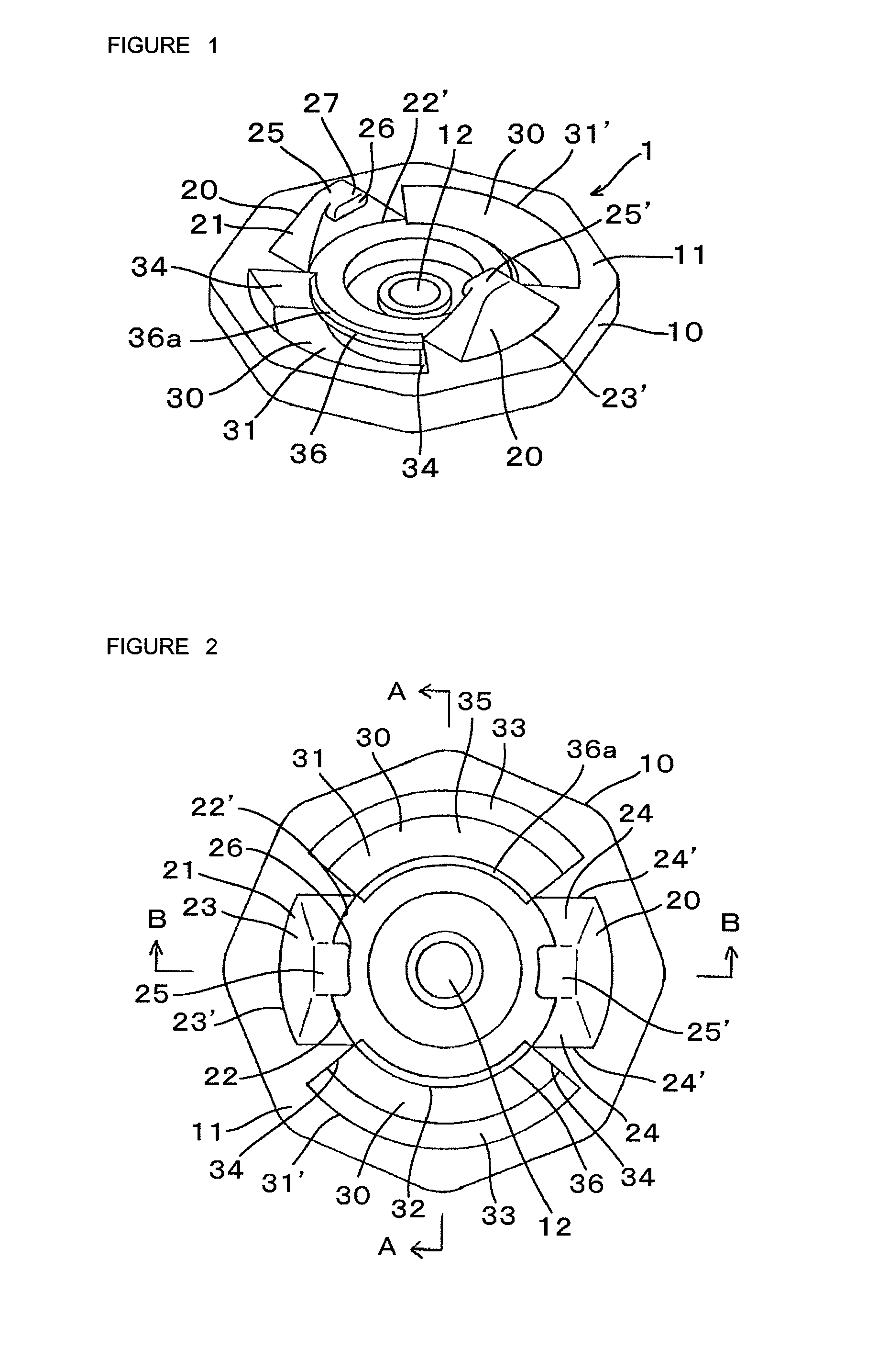
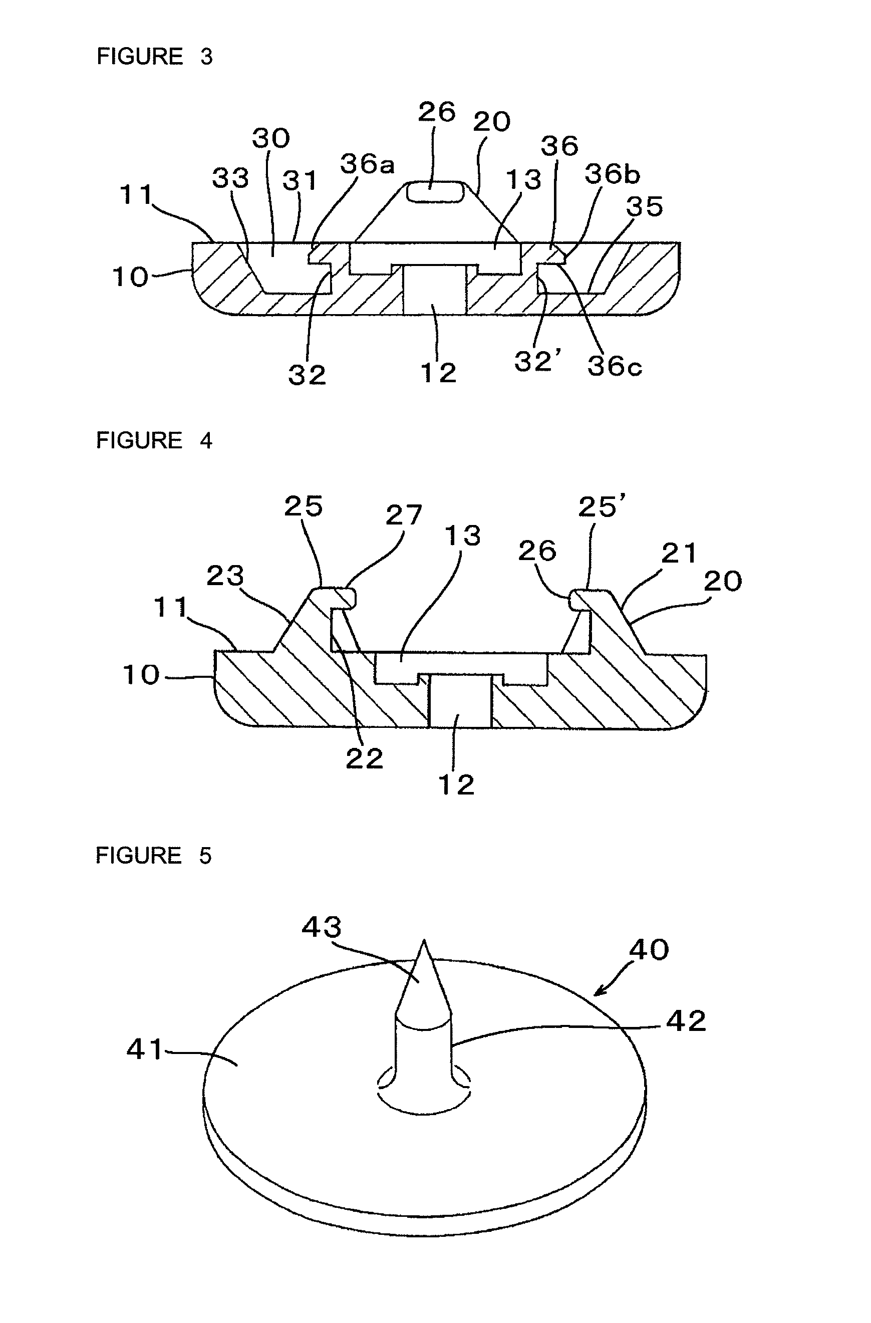
[0026]Hereinafter, preferred embodiments of the invention will be described with referring to the drawings. FIGS. 1 and 2 are a perspective view and a plane view of a snap button 1 which can function as both of a male snap and a female snap according to an embodiment of the present invention. FIGS. 3 and 4 are sectional views taken along line A-A and line B-B in FIG. 2, respectively. The snap button 1, which is a molded resinous product, comprises a button body 10 having an octagonal disk-like shape, for example. To an upper surface 11 (the upper and lower directions are based on FIG. 4) of the button body 10, concavity and convexity such as projections 20 and recesses 30 as described later are formed. The button body 10 includes a axially through hole 12 at the center portion thereof for receiving a post 42 of an attaching member 40 (see FIG. 5 etc.) as mentioned later when the snap button 1 is attached to a cloth. Above the hole 12, there is provided a circular depression 13 conca...


PUM

PropertyMeasurementUnit
angleaaaaaaaaaa
angleaaaaaaaaaa
shapeaaaaaaaaaa

Abstract

A snap button is provided, which can function as both of a male snap and a female snap without accurate alignment or positioning two snap buttons to be engaged with each other. The snap button comprises a button body, wherein the button body includes a plurality of projections and a plurality of recesses, which are circumferentially alternately arranged. Each of the projections includes at least one salient and each of the recesses includes at least one protrusion. Each of the projections may be shaped as a horizontal cross-section thereof gradually decreases from the proximal end to the distal end. Further, the circumferential range of each recess is larger than that of each projection. The protrusion may have one or more cutouts, and the salient may be hemispherically shaped.

Description

[0001]This application is a national stage application of PCT / JP2009 / 053211, which is incorporated herein by reference.BACKGROUND OF THE INVENTION[0002]The present invention relates to a snap button used for clothes, bags and the like, more particularly, to a snap button which can function as both of a male snap and a female snap.[0003]In general, a snap button is used as a pair of a male snap and a female snap, where the male snap has a projection and the female snap has a recess for detachably receiving the projection of the male snap. Therefore, between the male and the female snaps, steps of manufacture, inventory management, attachment to cloths, etc. are different. To improve this matter, Japanese Examined Utility-Model H06-31929 discloses a technology in which one sort of a snap button can be used as both of a male snap and a female snap. The snap button disclosed in the document includes a pair of male pieces and a pair of female pieces both of which project from a disk-shap...

Claims


Application Information

Patent Timeline
Patent Type & Authority Patents(United States)
IPC IPC(8): A44B17/00
CPCA44B17/0029A44B17/0041Y10T24/36Y10T24/3685Y10T24/3683Y10T24/45178Y10T24/45958Y10T24/45257
Inventor TANIGUCHI, KATSUHIDESUZUKI, SAORI
Owner YKK CORP
Why Eureka
Try Eureka