
Percutaneous posterolateral spine fusion

a posterolateral spine and percutaneous technology, applied in the field of minimally invasive and percutaneous surgeries, can solve the problems of not revealing the push of bone fusion substance via a delivery tube to the decorticated transverse process, abnormal and painful motion, and requiring cumbersome application of bone matrix or bone fusion substan

Active Publication Date: 2013-07-16
KORNEL EZRIEL E
View PDF10 Cites 7 Cited by
  • Summary
  • Abstract
  • Description
  • Claims
  • Application Information

AI Technical Summary

Benefits of technology

This patent describes a method for performing a spine fusion procedure where a decorticator is used to remove bone marrow from a spine region, and a bone fusion substance is then pushed into that region using a pusher instrument. The procedure can be performed using a delivery tube that is inserted through a dilator, trocar, or guide wire, and the instruments can be malleable or adjustable to the spine's curvature. The technical effects of this method include improved bone growth and stability, reduced pain, and a simpler and more efficient procedure compared to previous methods. A system for performing the procedure is also described.

Problems solved by technology

Such abnormal and painful motion can be caused by proximity of discs, abnormal slippage of the vertebrae and other degenerative spinal conditions.
However, this technique requires multiple incisions in the patient's body and requires cumbersome application of the bone matrix or bone fusion substance.
Further, these references do not disclose pushing the bone fusion substance via a delivery tube to the decorticated transverse processes or to other areas of interest.

Method used


Image

  • Percutaneous posterolateral spine fusion
  • Percutaneous posterolateral spine fusion
  • Percutaneous posterolateral spine fusion

Examples


Embodiment Construction

[0016]Embodiments of the present invention will now be described with reference to the above-identified figures of the Drawings. However, the Drawings and the description herein of the invention are not intended to limit the scope of the invention. It will be understood that various modifications of the present description of the invention are possible without departing from the spirit of the invention. Also, features or steps described herein may be omitted, additional steps or features may be included, and / or features or steps described herein may be combined in a manner different from the specific combinations recited herein without departing from the spirit of the invention, all as understood by those of skill in the art.

[0017]FIG. 3 shows a vertebra 30 of the lumbar region of a human spine. The vertebra 30 includes a transverse process 32, the inferior articular process 33, the mamillary process 34, the accessory process 35 and the superior articular process 36. The vertebra 30...


PUM


Abstract

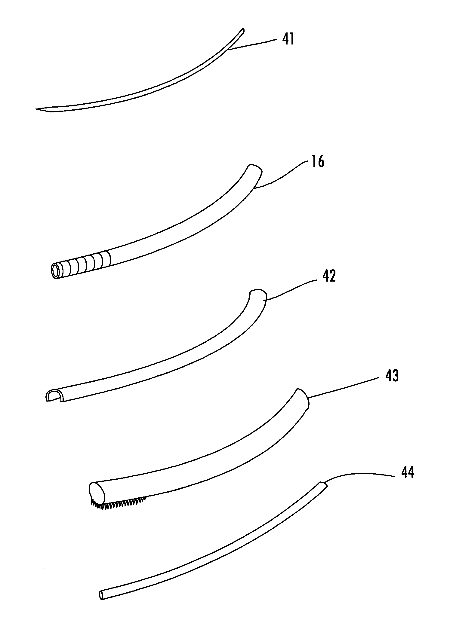
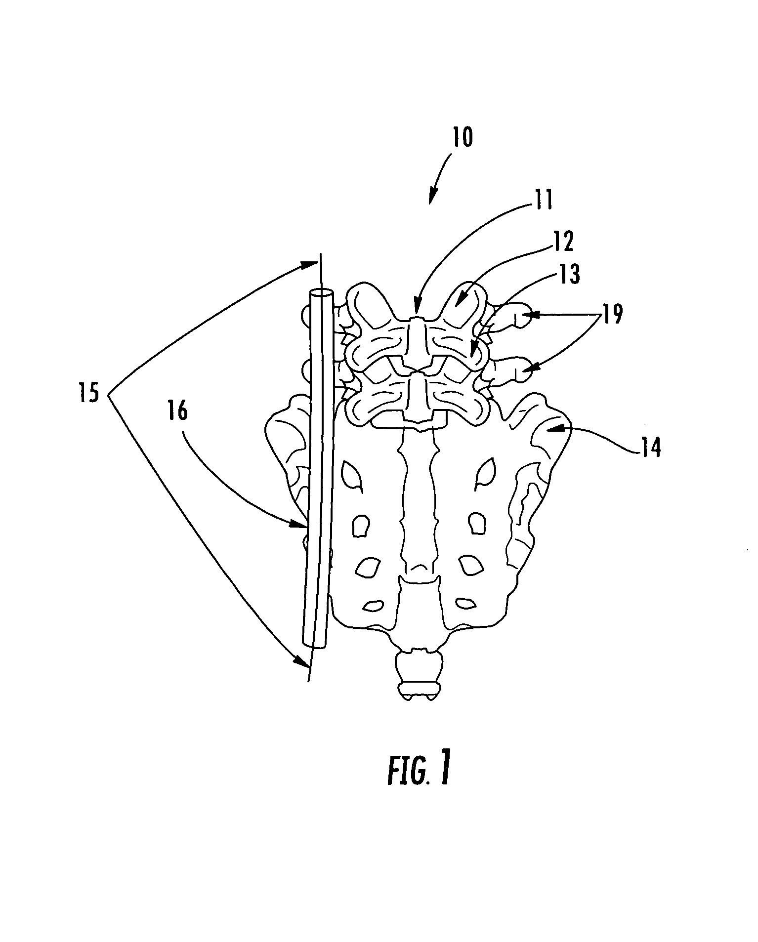
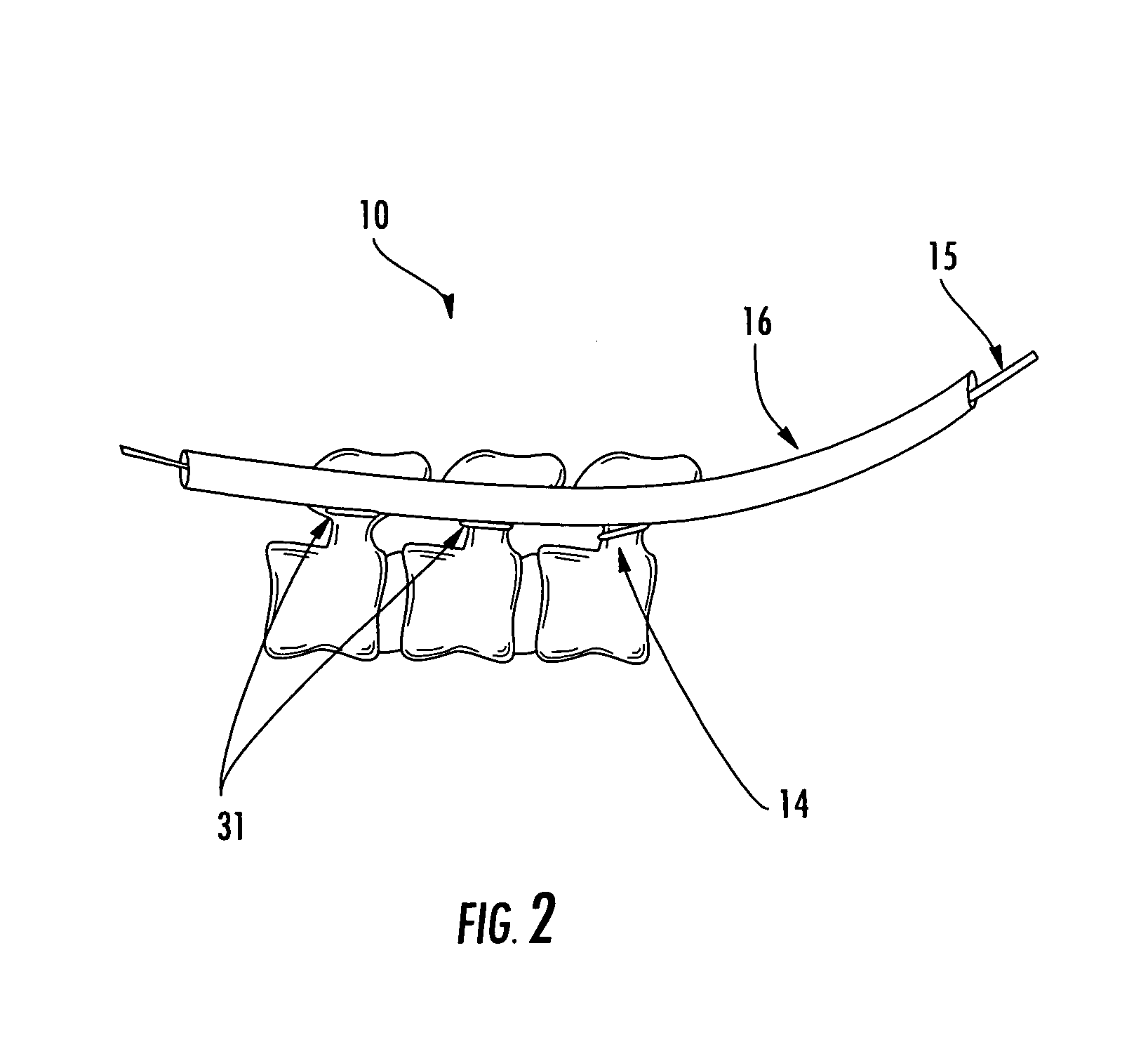
A method, tools, and system for performing a percutaneous or minimally invasive spine fusion procedure are provided. A trocar and then dilator are used to create a channel for a hollow and longitudinally slit delivery tube. The method includes inserting a decorticator, such as a rasp, via a delivery tube, decorticating a first region of a first bone associated with a spine, and pushing a bone fusion substance via the delivery tube to the region to fuse the first region with a second region of a second bone associated with the spine. The spine fusion may be a posterolateral fusion and the first region may be a transverse process region of a lumber spine. The bone fusion substance may be pushed using a pusher instrument inserted into the delivery tube, and the delivery tube may be removed while the pusher instrument is held in place to direct the bone fusion substance.

Description

RELATED APPLICATIONS[0001]This application claims priority to U.S. Provisional Patent Application Ser. No. 60 / 756,711, filed Jan. 5, 2006, the disclosure of which is incorporated herein by reference.FIELD OF THE INVENTION[0002]The present invention relates to the field of minimally invasive and percutaneous surgeries and related procedures, such as posterolateral spine fusion, including lumbar spine fusion at the transverse processes, and to medical instruments for performing the same.BACKGROUND OF THE INVENTION[0003]Certain types of spine disease caused by painful relative motion of vertebrae of the spine warrant a procedure known as spinal fusion. Such abnormal and painful motion can be caused by proximity of discs, abnormal slippage of the vertebrae and other degenerative spinal conditions. In addition, certain conditions involving instability of the spine, and certain types of fractures, infections, deformities or tumors may also warrant spinal fusion.[0004]Traditionally, an ope...

Claims


Application Information

Patent Timeline
Patent Type & Authority Patents(United States)
IPC IPC(8): A61B17/56A61B17/32
CPCA61B17/1659A61B17/7074A61B17/1671A61B17/1757A61B17/3417A61B17/1697A61B2017/90A61B17/90
Inventor KORNEL, EZRIEL E.
Owner KORNEL EZRIEL E
Learn More