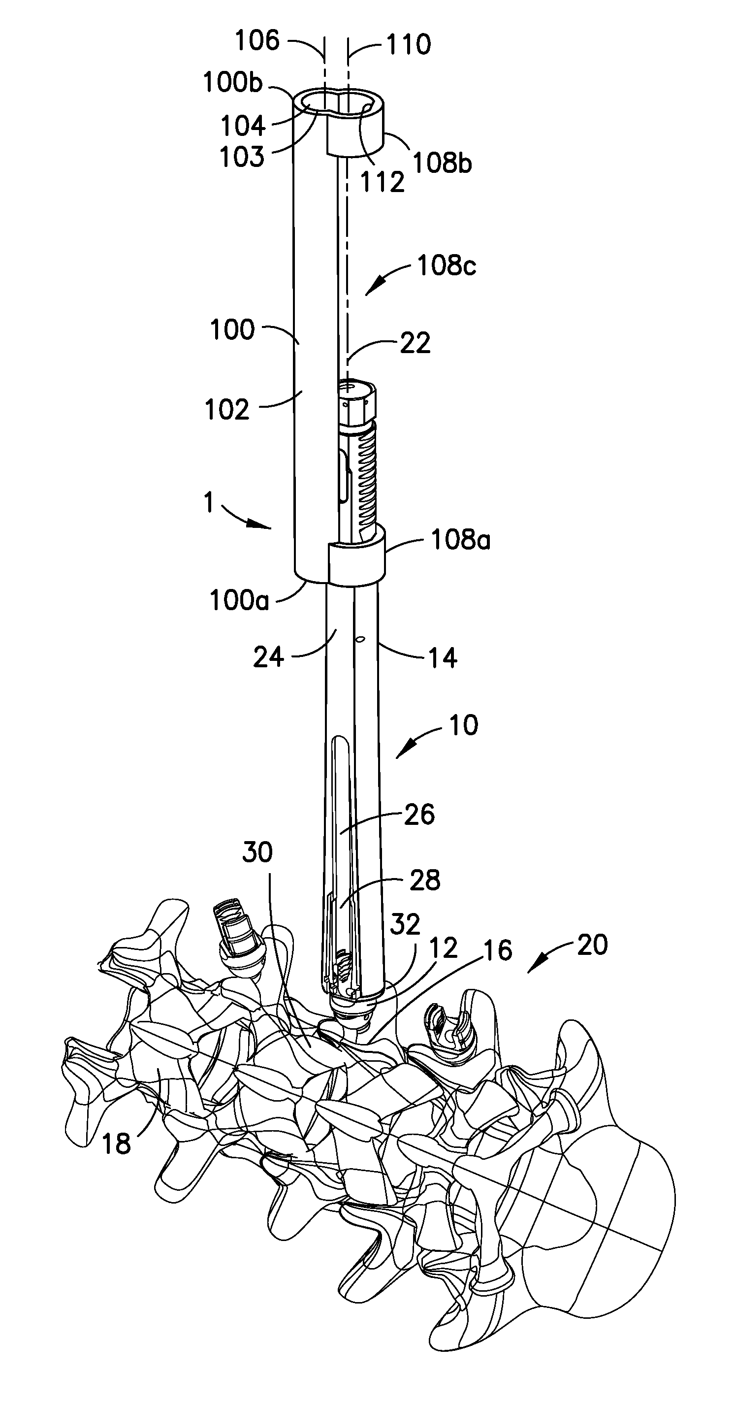

Minimally invasive posterolateral fusion

a posterolateral and minimally invasive technology, applied in the field of minimally invasive spinal fusion, can solve the problems of limited mobility, difficult to direct access and visualize the midline and lateral elements of the vertebral body, and not allow multiaxial motion

Active Publication Date: 2015-12-31
SPINEWAVE
View PDF20 Cites 21 Cited by
  • Summary
  • Abstract
  • Description
  • Claims
  • Application Information

AI Technical Summary

Benefits of technology

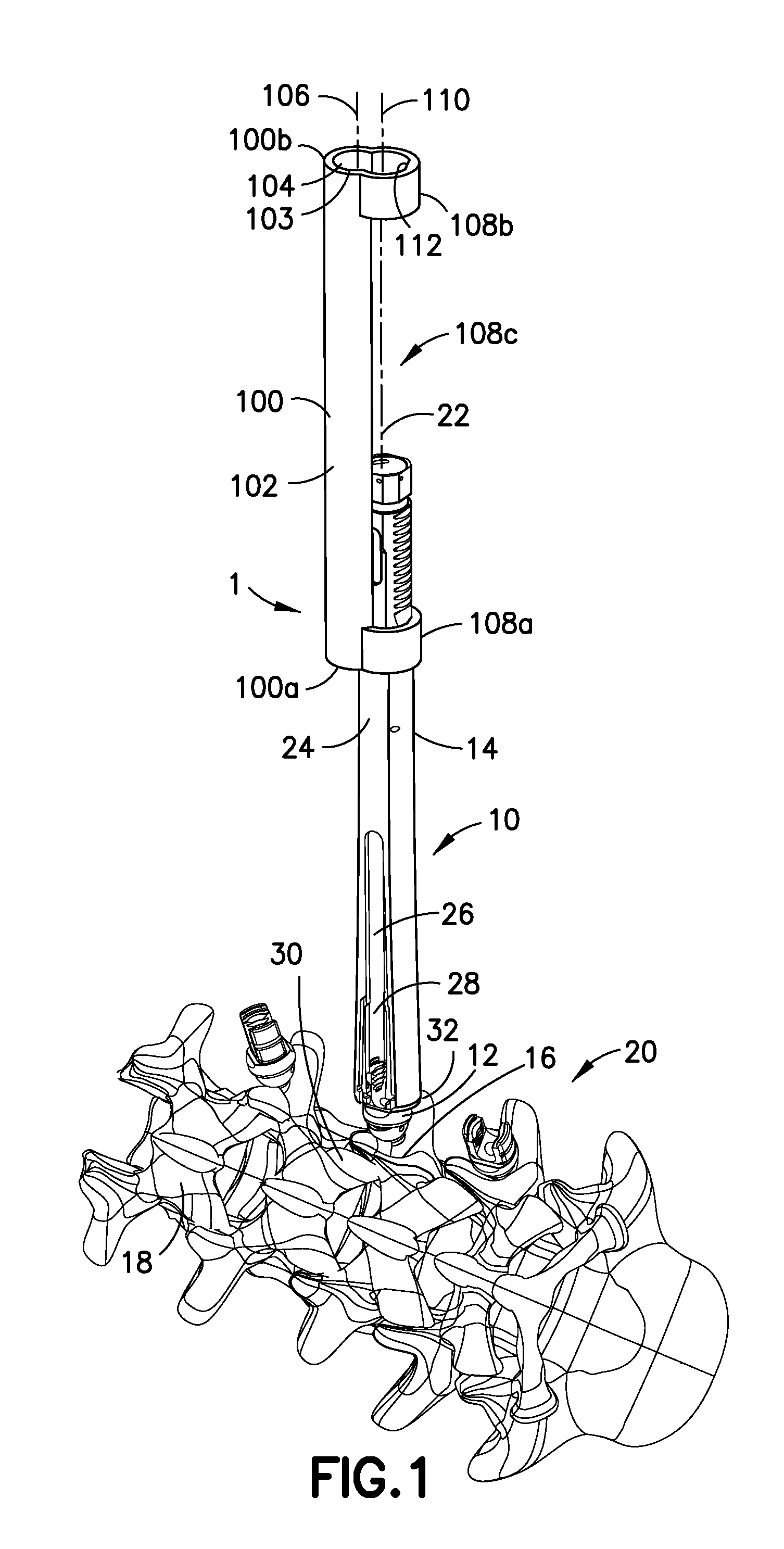
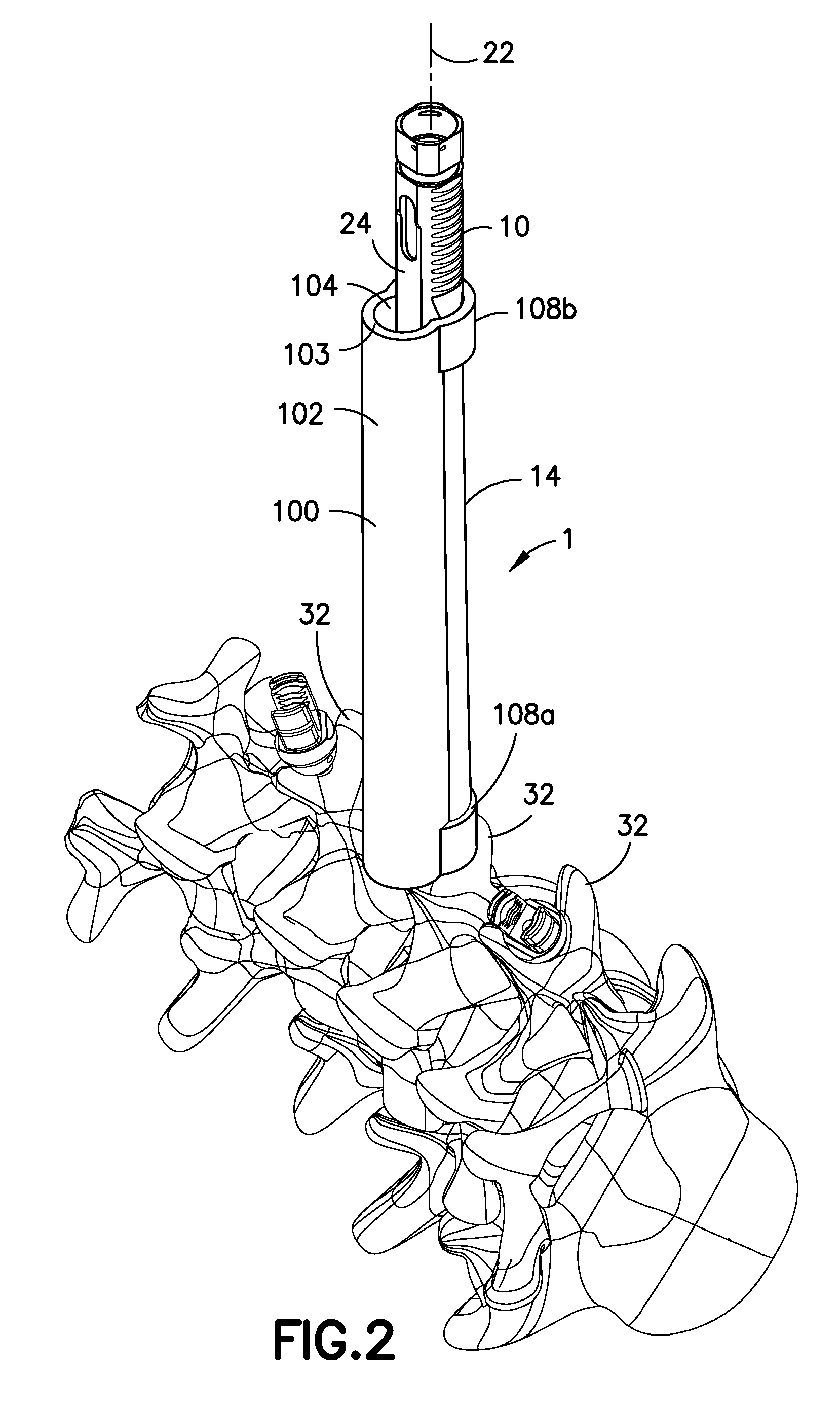
The invention provides a system for accessing the posterior spinal elements during spinal fusion. A series of tubular retractors is fixed percutaneously to screw extensions to create a pathway to the bones. The surgeon can use direct vision or endoscopy to see the surgical area. The system allows for minimally invasive access and preparation of the spinal bones for graft delivery. A synthetic bone graft can be applied directly at the surgery site or along the sp adults. The system balances visualization with minimizing tissue damage and provides a controlled and known access corridor to the posterior spinal elements. The invention also provides methods for preparing a graft channel between the spinal elements.

Problems solved by technology

With the advent of minimally invasive spinal fusion, direct access and visualization of the midline and lateral elements of the vertebral bodies have been difficult to perform in a minimally invasive manner, while access to the disc has been done with tubular retractors dilating tissues and muscle layers.
However the anchor points for these tubular elements have generally been of a fixed nature and do not allow for the multiaxial motion of the delivery system needed for broad access and visualization of the midline and lateral bony elements.
For example, Oktavec et al. in U.S. Patent Application Publication No. 2012 / 0253316, entitled “Percutaneous Biologic Delivery System”, filed Mar. 28, 2012, disclose such a fixed anchor point where the pivot points are distal from the fixed pin based anchor point and therefore have limited mobility.
In addition, the pivoting element is relatively distant from the anchor element, which will tend to result in a more significant retraction of the surrounding tissues and muscle.

Method used


Image

  • Minimally invasive posterolateral fusion
  • Minimally invasive posterolateral fusion
  • Minimally invasive posterolateral fusion

Examples


Embodiment Construction

[0045]For the purposes of promoting and understanding of the principles of the invention, reference will now be made to the embodiments illustrated in the drawings and described in the following written specification. It is understood that no limitation to the scope of the invention is thereby intended. It is further understood that the present invention includes any alterations and modifications to the illustrated embodiments and includes further applications of the principles of the invention as would normally occur to one skilled in the art to which this invention pertains.

[0046]As set forth herein, the subject invention provides the ability to visualize and access surrounding bony elements and soft tissues in a mobile manner while utilizing a well-established anchor point in the pedicle of spinal vertebrae. Instrumentation necessary for soft tissue preparation and bony removal may be placed either directly through the access port, through access slots in the side of the tubular ...


PUM


Abstract

A percutaneous system in which tubular retractors are utilized as a means of access, visualization, and a controlled orientation for preparation of posterior spinal elements and delivery of graft material for posterior spinal fusion. The tubular retractors are affixed to screw extensions to rotate and articulate relative to multi-axial screws percutaneously inserted into respective pedicles of vertebral bodies. The procedure is done bilaterally, although it could be performed unilaterally in cases where the anatomy or surgeon preference dictates. A number of different deployable graft concepts are disclosed, the primary features being to allow for creation of a graft space volume and a means for delivery of the graft material preferred by the surgeon.

Description

CROSS-REFERENCE TO RELATED APPLICATION[0001]This application claims the benefit of U.S. Provisional Patent Application No. 62 / 016,743, filed Jun. 25, 2014, the entire contents of which are incorporated by reference herein.FIELD OF THE INVENTION[0002]The subject invention relates generally to the field of minimally invasive spinal fusion and more particularly to a minimally invasive method for achieving a posterolateral spinal fusion. The subject technique may be used as an augment for a minimally invasive interbody spinal fusion. It may also be helpful as a sole fusion site for a distal level fusion during cases where interbody fusion may not be achievable, for example in long deformity fusions or very challenging spinal anatomy.BACKGROUND OF THE INVENTION[0003]Current methods of minimally invasive spinal fusion primarily focus on the interbody space and use of an interbody spinal implant with bone grafting inside the intervertebral disc space. Traditionally, surgeons have performed...

Claims


Application Information

Patent Timeline
Patent Type & Authority Applications(United States)
IPC IPC(8): A61B17/02A61B17/88A61B17/70A61B17/34A61M29/00
CPCA61B17/1757A61F2/4601A61B17/7077A61B17/3421A61B17/3423A61B17/8802A61B2017/3447
Inventor BOYD, LAWRENCE M.RATCLIFFE, JR., JOHN J.MORIN, JOSHUAMARIGOWDA, SHRESTAADAMSON, TIM E.ROBBINS, DANIELBARBIERI, THOMAS J.
Owner SPINEWAVE
Learn More