
Device and method for optical 3D measurement and for color measurement

a technology of optical 3d and color measurement, applied in the field of optical 3d measurement and color measurement, can solve the problems of laborious information acquisition and either suitabl

Inactive Publication Date: 2013-07-16
SIRONA DENTAL SYSTEMS
View PDF8 Cites 119 Cited by
  • Summary
  • Abstract
  • Description
  • Claims
  • Application Information

AI Technical Summary

Benefits of technology

[0018]An advantage is that both 3D measurement and color measurement can be carried out by means of the device of the invention. The same light source emitting a broad-band illuminating beam and the same color sensor are used for both modes. In dentistry, in particular, the 3D measurement and color measurement of teeth for the purpose of designing dental prosthetic items is made possible by the use of a single device of the invention.
[0093]Advantageously, the intensity of the light source can be adjusted such that the decrease in the quantity of light in the second mode due to the presence of a smaller diameter of the diaphragm can be compensated for by an increase in the intensity of the light source so as to make colorimetric measurement possible.

Problems solved by technology

A disadvantage of such devices is that they are either suitable only for 3D measurement or only for color measurement.
Therefore, this information is acquired laboriously firstly by means of known devices for 3D measurement and secondly by means of known devices for color measurement, the two processes being carried out independently of each other.

Method used


Image

  • Device and method for optical 3D measurement and for color measurement
  • Device and method for optical 3D measurement and for color measurement
  • Device and method for optical 3D measurement and for color measurement

Examples


Embodiment Construction

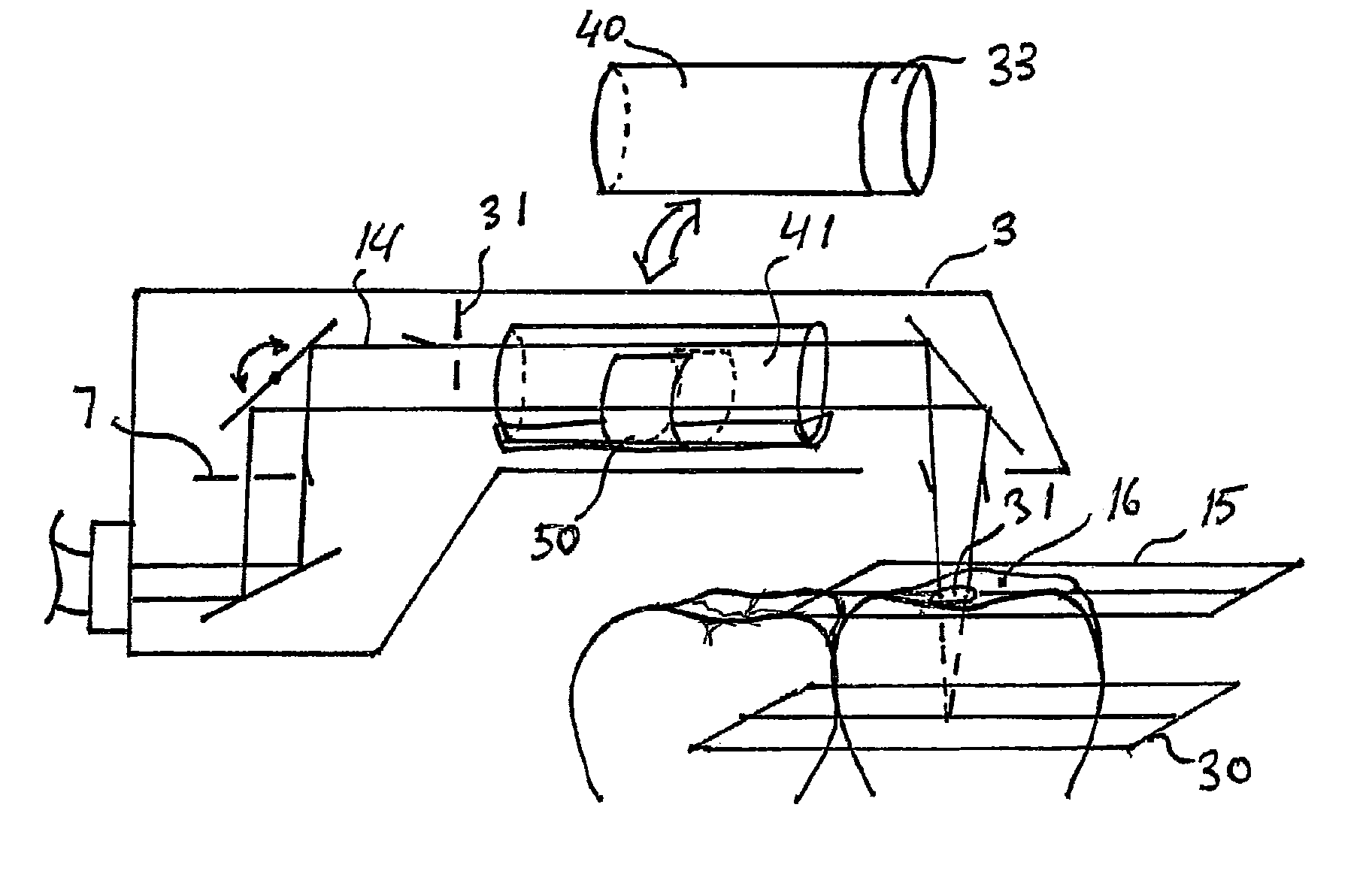
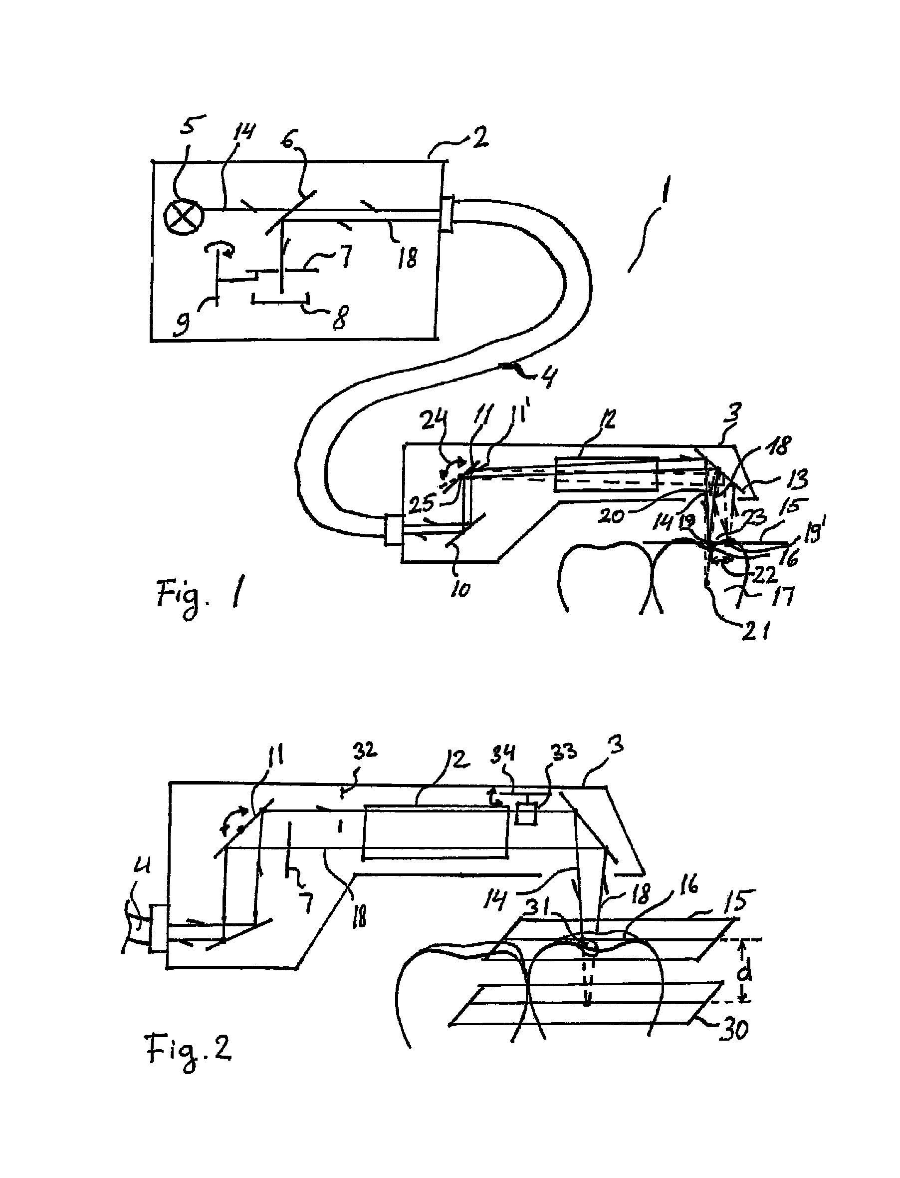
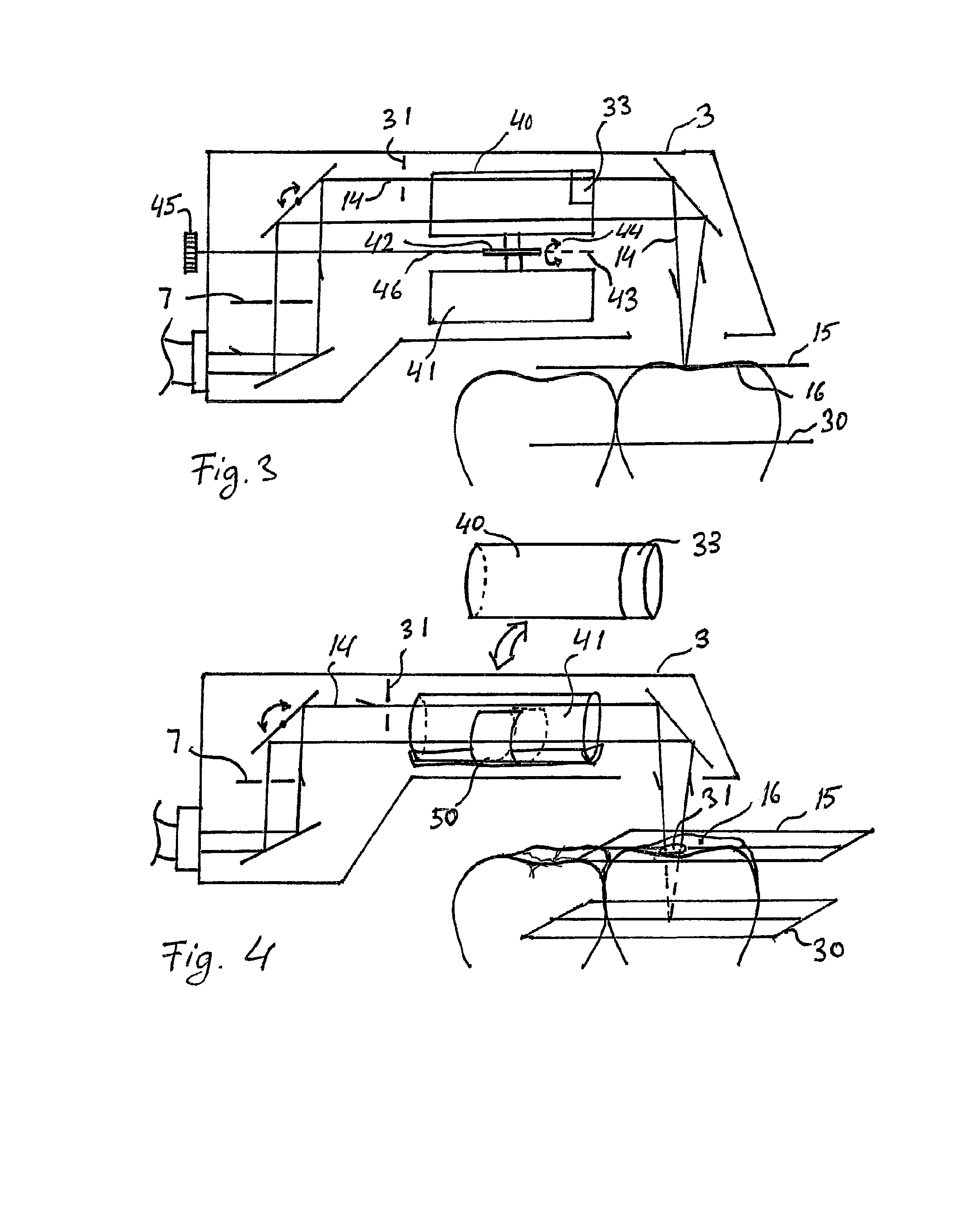
[0105]FIG. 1 shows the device 1 of the invention for optical 3D scanning and for colorimetric measurement comprising a base unit 2 and a handpiece 3 that are interconnected by means of a light guide 4. The base unit 2 comprises a light source 5, a beam splitter 6, a diaphragm 7, and a color sensor 8. The diaphragm 7 is mounted for rotation about an axis 9 and can be rotated laterally. The handpiece 3 comprises a first permanently installed deflection mirror 10, a rotating mirror 11, an objective 12, and a third deflection mirror 13. The light source 5 emits an illuminating beam 14 that passes through the semi-transparent beam splitter 6 and is directed by means of the light guide 4 toward the handpiece 3. Here, the illuminating beam is deflected by the first deflection mirror 10 toward the rotating mirror 11 and is deflected by the rotating mirror 11 in the direction of the third deflection mirror 13. The illuminating beam is focused by means of the objective 12 onto a first plane 1...


PUM

PropertyMeasurementUnit
color temperatureaaaaaaaaaa
depth of focusaaaaaaaaaa

Abstract

The invention relates to a device and a method for optical 3D measurement, wherein said device can be switched between a first mode for optical 3D measurement using a chromatic confocal measurement method or the triangulation measurement method and a second mode for colorimetric measurement. In the first mode, a broad-band illuminating beam is focused onto a first plane and in the second mode the broad-band illuminating beam is focused onto a second plane other than the first plane at a distance d from the surface of the object to be measured.

Description

CROSS REFERENCE TO RELATED APPLICATIONS[0001]This application is a continuation of International Application No. PCT / EP2009 / 053912, filed Apr. 2, 2009, and claims priority to German Patent Application No. 102008017481.5, filed Apr. 3, 2008, each of which is incorporated by reference herein in its entirety, as if set forth fully herein.TECHNICAL FIELD[0002]The invention relates to a device and method for optical 3D measurement and for color measurement.PRIOR ART[0003]A number of devices for optical 3D measurement are known in the prior art. The devices are often based on optical measuring methods such as the chromatic confocal measuring method or the triangulation measuring method.[0004]Furthermore, devices used for colorimetric measurement are known in the prior art. In the method for color measurement, the object to be measured is illuminated by a light beam having a spectrum similar to daylight and the reflected light beam is detected by means of a color sensor such as a CCD camer...

Claims


Application Information

Patent Timeline
Patent Type & Authority Patents(United States)
IPC IPC(8): G01N21/00
CPCG01B11/026G01B11/2509G01J3/02G01J3/0208G01J3/021G01J3/0229G01J3/0235G01J3/0237G01J3/10G01J3/50G01J3/508G01N21/255G02B21/0028G02B21/0032G02B21/0064A61C9/0053G01B2210/50G01B11/24
Inventor THIEL, FRANKFORNOFF, PETER
Owner SIRONA DENTAL SYSTEMS
Learn More