
Fast-settling precision voltage follower circuit and method

a follower circuit and precision technology, applied in the direction of differential amplifiers, amplifiers with semiconductor devices/discharge tubes, instruments, etc., can solve the problem of not providing the short settling time required for a capacitive touch screen application

Active Publication Date: 2013-07-23
TEXAS INSTR INC
View PDF2 Cites 6 Cited by
  • Summary
  • Abstract
  • Description
  • Claims
  • Application Information

AI Technical Summary

Benefits of technology

[0013]It is another object of the invention to provide a precision voltage follower circuit and method which provide a very fast-settling output voltage while driving a very large capacitive load.
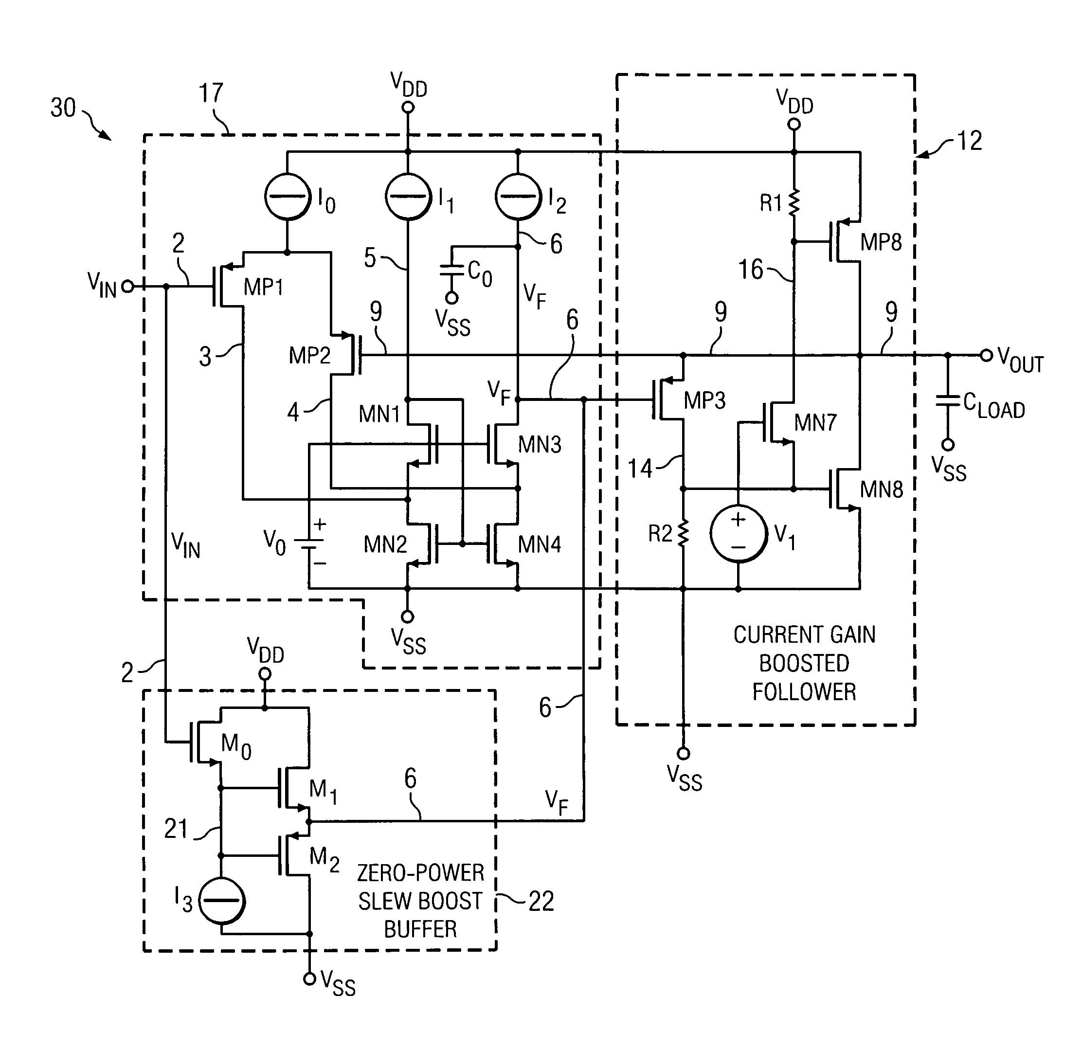
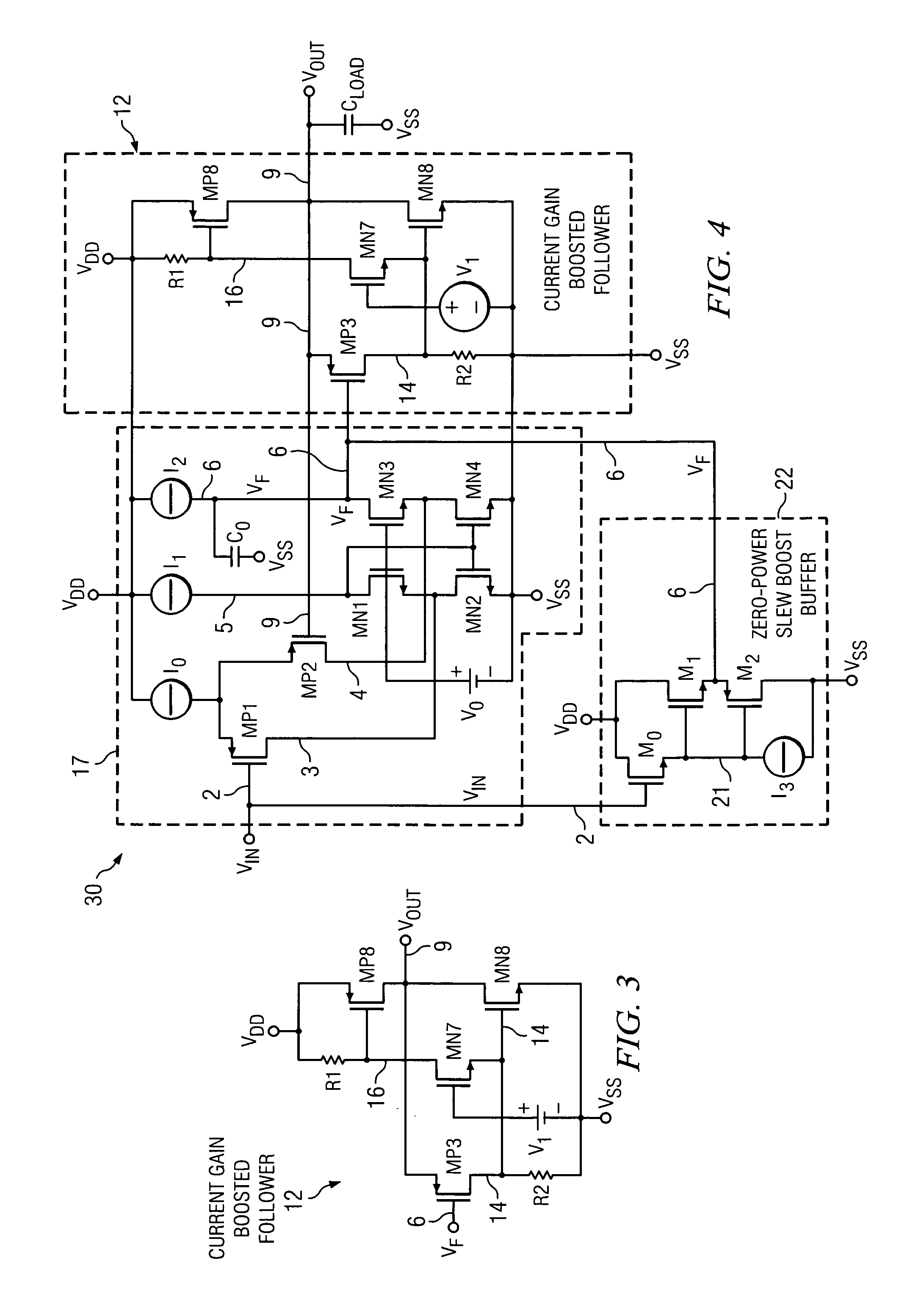
[0028]In one embodiment, if the first signal (VF) 3 undergoes a fast, negative-going transition, the method includes turning the follower transistor (MP3) on to cause a voltage developed across the first resistive element (R2) to rapidly increase, turning the pull-down transistor (MN8) on in response to the increased voltage across the first resistive element (R2), reducing current through the cascode transistor (MN7) in response to the increased voltage across the first resistive element (R2), turning the pull-up transistor (MP8) off in response to decreased current through the cascode transistor (MN7), and rapidly decreasing the voltage of the output signal (VOUT) in response to increased current through the pull-down transistor (MN8).

Problems solved by technology

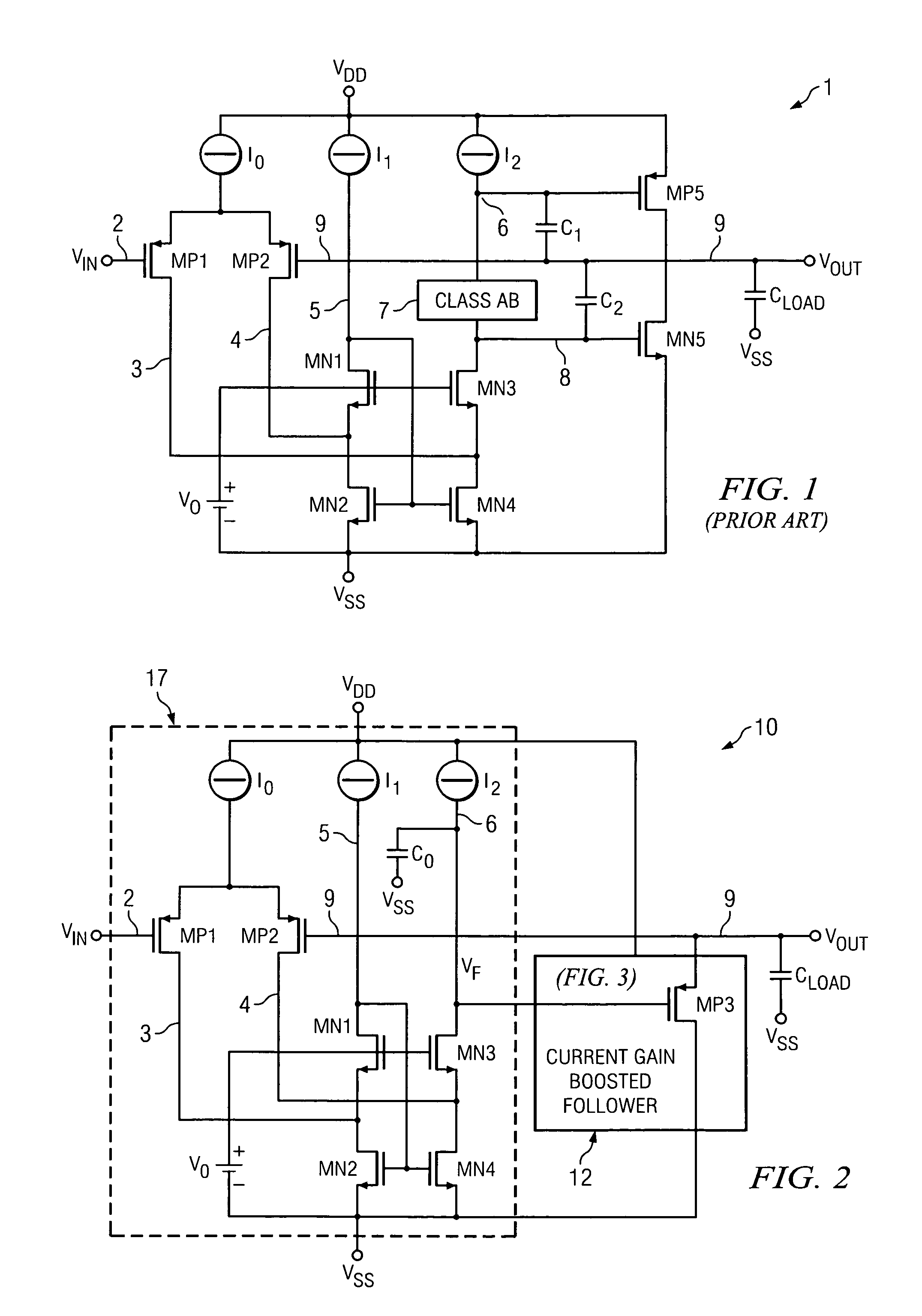
Although the operating speed of a standard LCD driver is not an issue because its back panel voltage is constant, the conventional two-stage voltage follower amplifier architecture shown in Prior Art FIG. 1 can not provide the short settling times required for a capacitive touch screen application in which there would be very fast, large (e.g., 5 volt) transitions or “steps” of the input voltage VIN.

Method used


Image

  • Fast-settling precision voltage follower circuit and method
  • Fast-settling precision voltage follower circuit and method
  • Fast-settling precision voltage follower circuit and method

Examples


Embodiment Construction

[0035]FIG. 2 is a schematic diagram of a single stage voltage follower amplifier 10. In FIG. 2, voltage follower amplifier circuit 10 includes a differential input stage 17 including P-channel input transistors MP1 and MP2 having their sources coupled to one terminal of a tail current source IO, the other terminal of which is connected to VDD. The gate of input transistor MP1 is connected by conductor 2 to receive an input voltage VIN. The gate of input transistor MP2 is connected to the output signal VOUT. on output conductor 9. The drain of input transistor MP1 is connected by conductor 3 to the junction between N-channel transistor MN2 and N-channel cascode transistor MN1. The drain of input transistor MP2 is connected by conductor 4 to the junction between N-channel transistor MN4 and N-channel cascode transistor MN3. The sources of transistors MN2 and MN4 are connected to VSS. The gates of cascode transistors MN1 and MN3 are connected to a voltage source V0. The gates of lower ...


PUM


Abstract

A voltage follower circuit including an input stage for generating a difference between the input signal and the output signal. An output circuit receiving the first signal and producing the output signal. A slew boost circuit includes a first transistor having a control electrode for receiving the input signal, a first electrode coupled to a first current source, and a second electrode coupled to a first supply voltage, a second transistor having a control electrode coupled to the first electrode of the first transistor, a first electrode coupled to the first signal, and a second electrode coupled to the first supply voltage, and a third transistor having a control electrode coupled to the first electrode of the first transistor, a first electrode coupled to the first signal, and a second electrode coupled to a second supply voltage.

Description

BACKGROUND OF THE INVENTION[0001]The present invention relates generally to fast-settling precision voltage follower circuits for driving large capacitive loads, and more particularly to a fast-settling precision voltage follower circuit that is suitable for applying a reference voltage input to the back panel conductor of an LCD panel.[0002]The back side conductor of an ordinary LCD panel should be maintained at an accurate, constant voltage since color and intensity of the image pixels are determined by the voltage between the back side conductor and any particular front pixel electrode. The capacitance of the back panel can be up to 15-20 nanofarads, depending on the panel size. However, if the LCD screen has capacitively coupled sensors on it which are used for touch sensing, the voltage between any particular front pixel electrode and the backside conductor must be rapidly switched to accommodate for different modes of sensing, while continuing to maintain the present image on ...

Claims


Application Information

Patent Timeline
Patent Type & Authority Patents(United States)
IPC IPC(8): G05F3/16H03F3/26H03F3/45
CPCH03F3/3022H03F3/45192H03F3/505H03F2203/30015
Inventor IVANOV, VADIM V.VENKATARAMAN, HARISHCURTIS, SUSAN A.
Owner TEXAS INSTR INC
Learn More