Pair of double staple pusher in triple row stapler

a staple pusher and triple-row technology, applied in the direction of surgical staples, paper/cardboard containers, manufacturing tools, etc., can solve the problems of non-uniform staple formation, twisting of the staple pusher within the grooved slot, and binding, etc., to facilitate the engagement of staples

Active Publication Date: 2013-07-30
TYCO HEALTHCARE GRP LP
View PDF18 Cites 1032 Cited by
  • Summary
  • Abstract
  • Description
  • Claims
  • Application Information

AI Technical Summary

Benefits of technology

[0009]In an embodiment, a staple pusher may include at least two pusher plates including top surfaces that are configured and adapted to engage a staple retained within one of the retention slots. The top surfaces of the pusher plates may be substantially symmetrical, with respect to one another, about a central longitudinal axis of the staple pusher. The pusher plates may be laterally spaced apart, i.e., spaced apart transverse to the central longitudinal axis. In addition, the pusher plates may have substantially equal dimensions and may be substantially positioned along the same points along the central longitudinal axis of the staple cartridge housing. The arrangement of the pusher plates facilitates engagement of staples within retention slots defined within a single column a single column and within separate rows of retention slots.

Problems solved by technology

Several issues arise in designing staple pushers for driving one or more surgical staples.
If the forces applied to the staple pusher are not effectively balanced, there is a tendency for the staple pusher to twist within the grooved slot and / or bind against the walls of the grooved slot.
Additionally, a single point of contact between the actuation sled and the staple pusher may create a rocking point on the staple pusher which can cause the staple pusher to exit the staple cartridge in an unbalanced manner which may result in non-uniform staple formation.

Method used


Image

  • Pair of double staple pusher in triple row stapler
  • Pair of double staple pusher in triple row stapler
  • Pair of double staple pusher in triple row stapler

Examples


Embodiment Construction

[0038]Particular embodiments of the present disclosure will be described herein with reference to the accompanying figures. In the following description, well known functions or constructions are not described in detail to avoid obscuring the present disclosure in unnecessary detail. As shown in the figures and as described throughout the following descriptions, and as is traditional when referring to relative positioning on an object, the term “proximal” refers to the end of the device that is closer to the user and the term “distal” refers to the end of the device that is farther from the user.

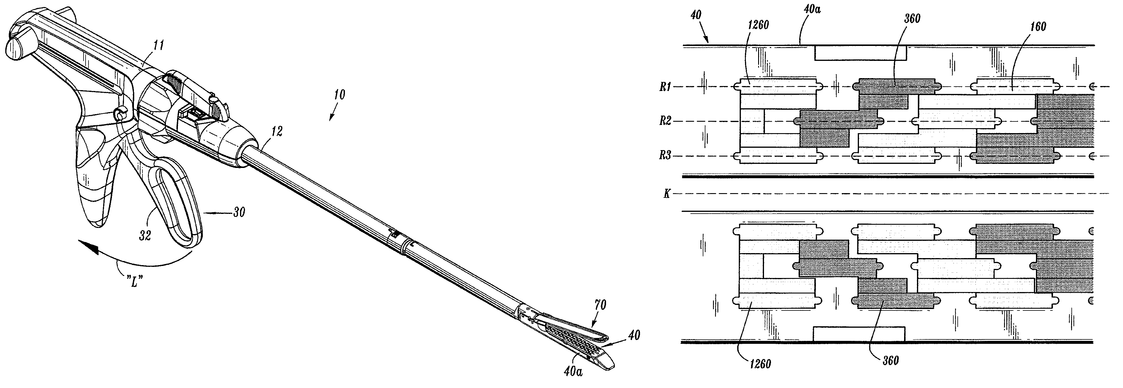
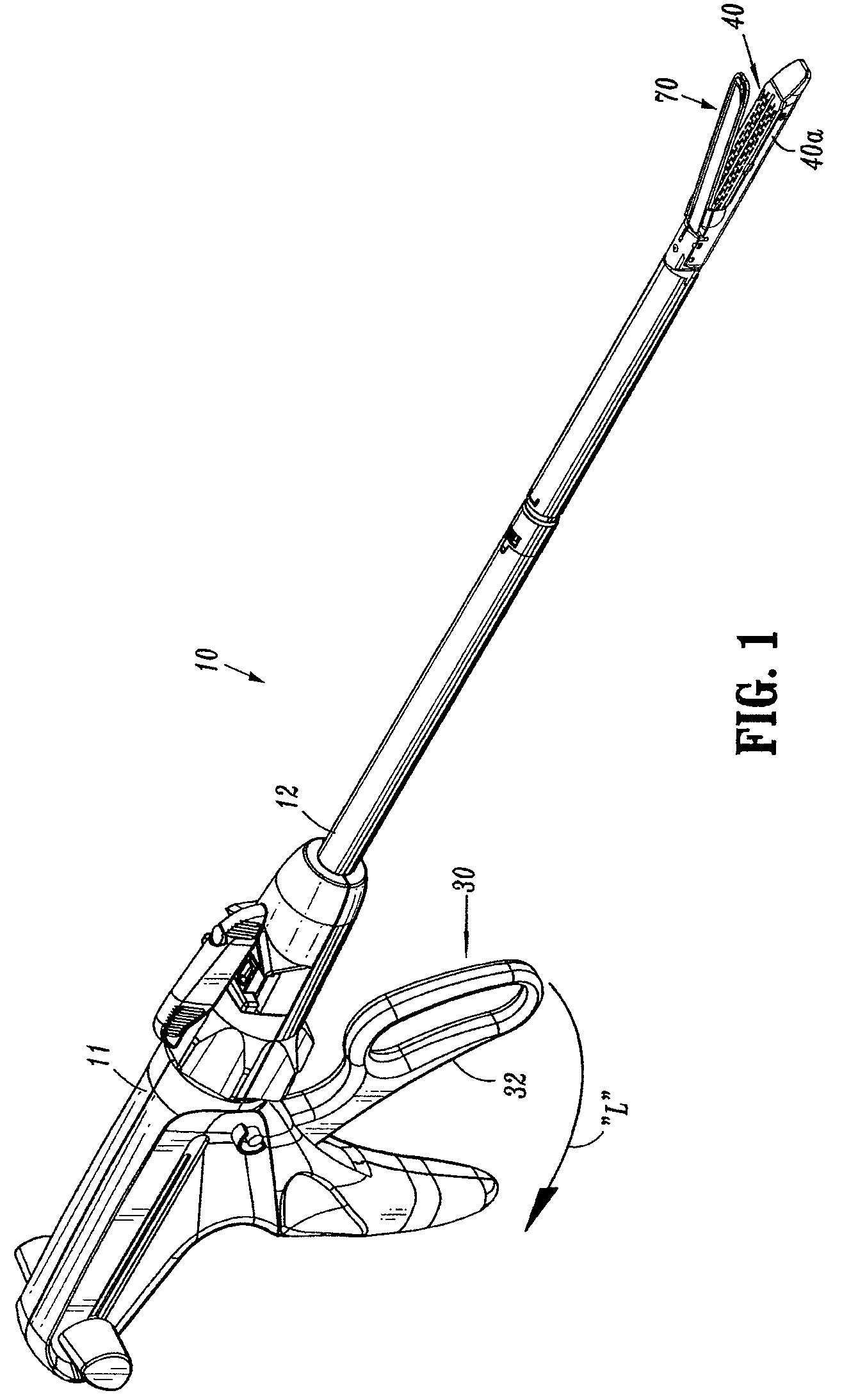
[0039]A surgical stapler 10 will now be described with reference to FIGS. 1-19. Surgical stapler 10, as shown in FIG. 1, includes a housing 11, a trigger assembly 30 pivotably coupled to the housing 11, a body portion 12 extending from the housing 11, a staple cartridge 40, and an anvil assembly 70. An example of a surgical stapler having linear rows is disclosed in U.S. Pat. No. 6,669,073 t...


PUM

PropertyMeasurementUnit
drive anglesaaaaaaaaaa

Abstract

A staple cartridge includes outer and inner rows of retention slots that are adapted and configured to retain staples. The staple cartridge further includes a staple pusher including a plurality of pusher plates. A staple pusher includes pusher plates that are laterally spaced apart to engage staples within the outer rows of at least three rows of retention slots.

Description

CROSS REFERENCE TO RELATED APPLICATIONS[0001]This application claims priority to, and benefit of, U.S. Provisional Application Ser. No. 61 / 249,637, filed Oct. 8, 2009, the disclosure of which is hereby incorporated by reference in its entirety.BACKGROUND[0002]1. Technical Field[0003]The present disclosure is related to a stapling apparatus and, more particularly, to a staple drive assembly for use in a staple cartridge of a stapling apparatus.[0004]2. Background of Related Art[0005]Surgical stapling devices are widely used in surgical procedures to fasten body tissue quickly and efficiently by driving fasteners or staplers into the tissue. In certain types of stapling devices, a drive member moves transversely to the direction the staples are to be driven. Typically, such stapling devices employ a number of staple pusher elements located in grooved slots of a staple cartridge and arranged end to end in rows. During normal operation, the transversely moving drive member contacts a ca...

Claims


Application Information

Patent Timeline
Patent Type & Authority Patents(United States)
IPC IPC(8): A61B17/068
CPCA61B17/068A61B17/07207A61B2017/07264A61B2017/07228A61B2017/07278A61B2017/00367A61B2017/0046A61B2017/07271A61B17/0644A61B17/0682A61B17/072A61B17/115A61B2017/07214A61B2017/07242
Inventor MARCZYK, STANISLAWOLSON, LEE
Owner TYCO HEALTHCARE GRP LP
Why Eureka
Try Eureka