Individual loading mechanism with simplified locking arrangement

a technology of individual locking and locking mechanism, which is applied in the direction of coupling device details, electrical apparatus construction details, coupling device connections, etc., can solve the problems of inability to keep up with the trend, take up a lot of space, and complicated assembly of electrical connectors, so as to achieve efficient pressing of cpu chips and simplify locking mechanisms

Inactive Publication Date: 2013-08-06
HON HAI PRECISION IND CO LTD
View PDF14 Cites 11 Cited by
  • Summary
  • Abstract
  • Description
  • Claims
  • Application Information

AI Technical Summary

Benefits of technology

[0007]Accordingly, an object of the present invention is to provide an ILM with simplified locking mechanism so as to efficiently press a CPU chip toward a socket connector mounted onto a printed circuit board.

Problems solved by technology

The assembly of the electrical connector is complicated.
It is also takes much more room and can't keep up with the trend of the electrical connector.

Method used


Image

  • Individual loading mechanism with simplified locking arrangement
  • Individual loading mechanism with simplified locking arrangement
  • Individual loading mechanism with simplified locking arrangement

Examples


Embodiment Construction

[0015]Reference will now be made to the drawings to describe the present invention in detail.

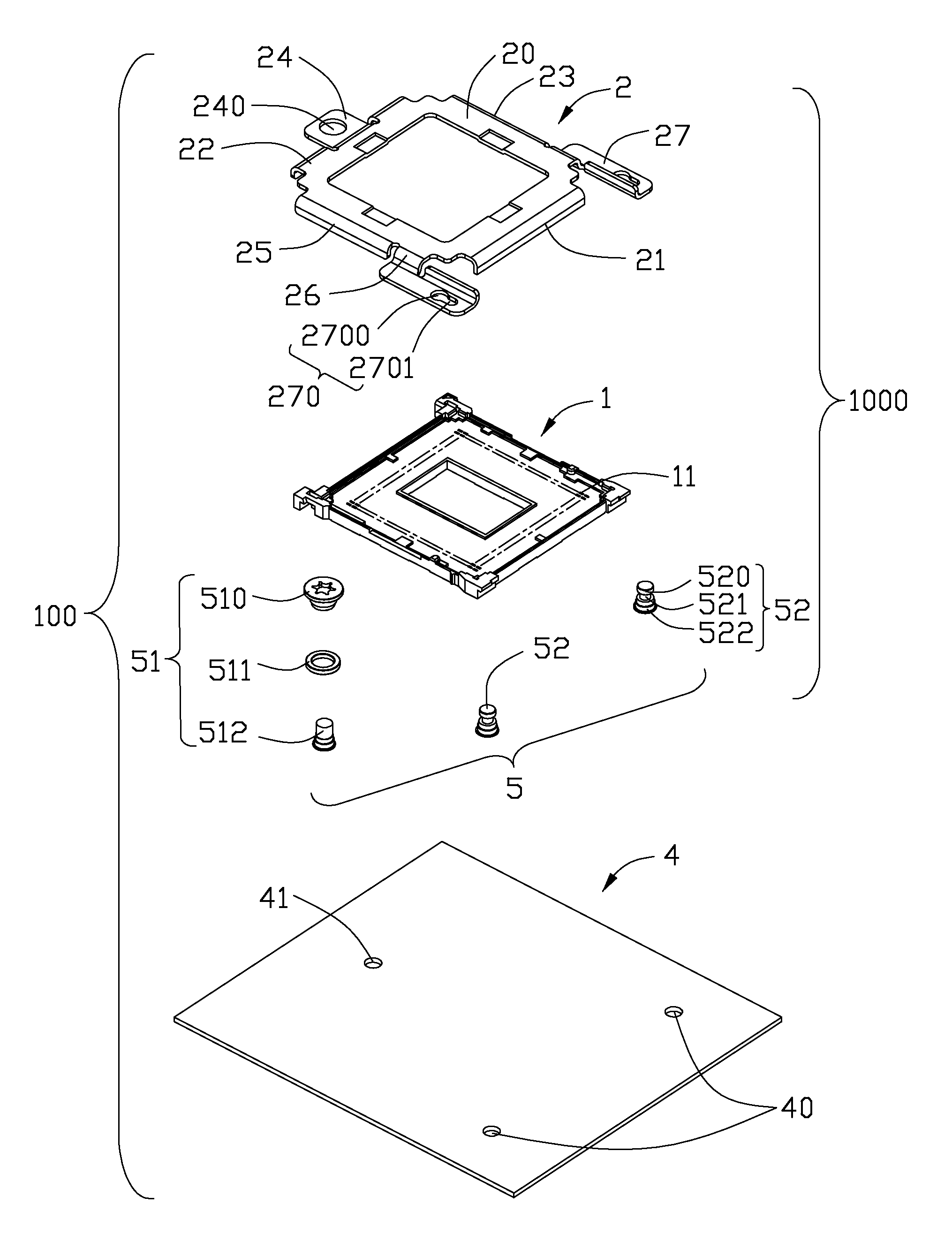
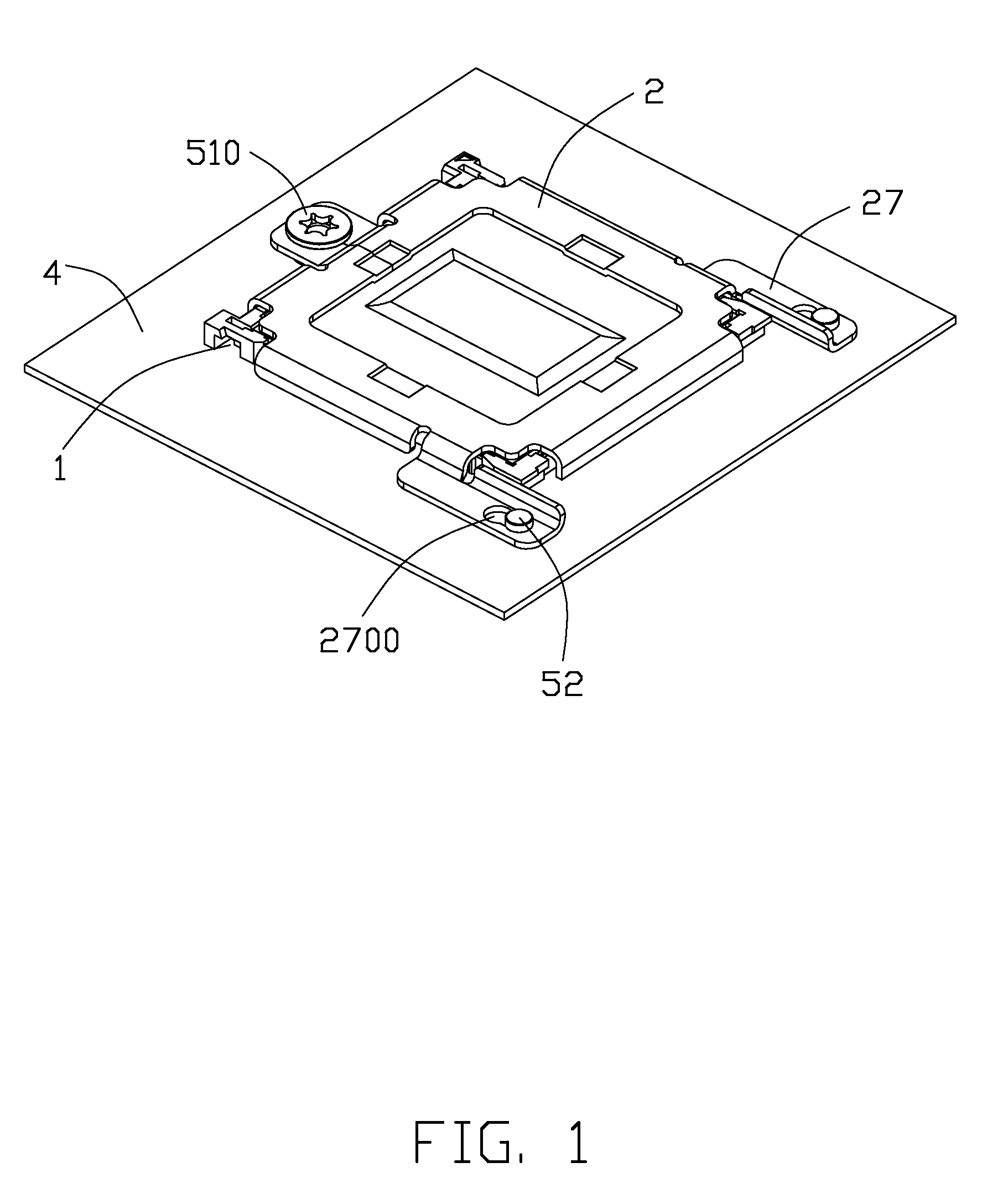
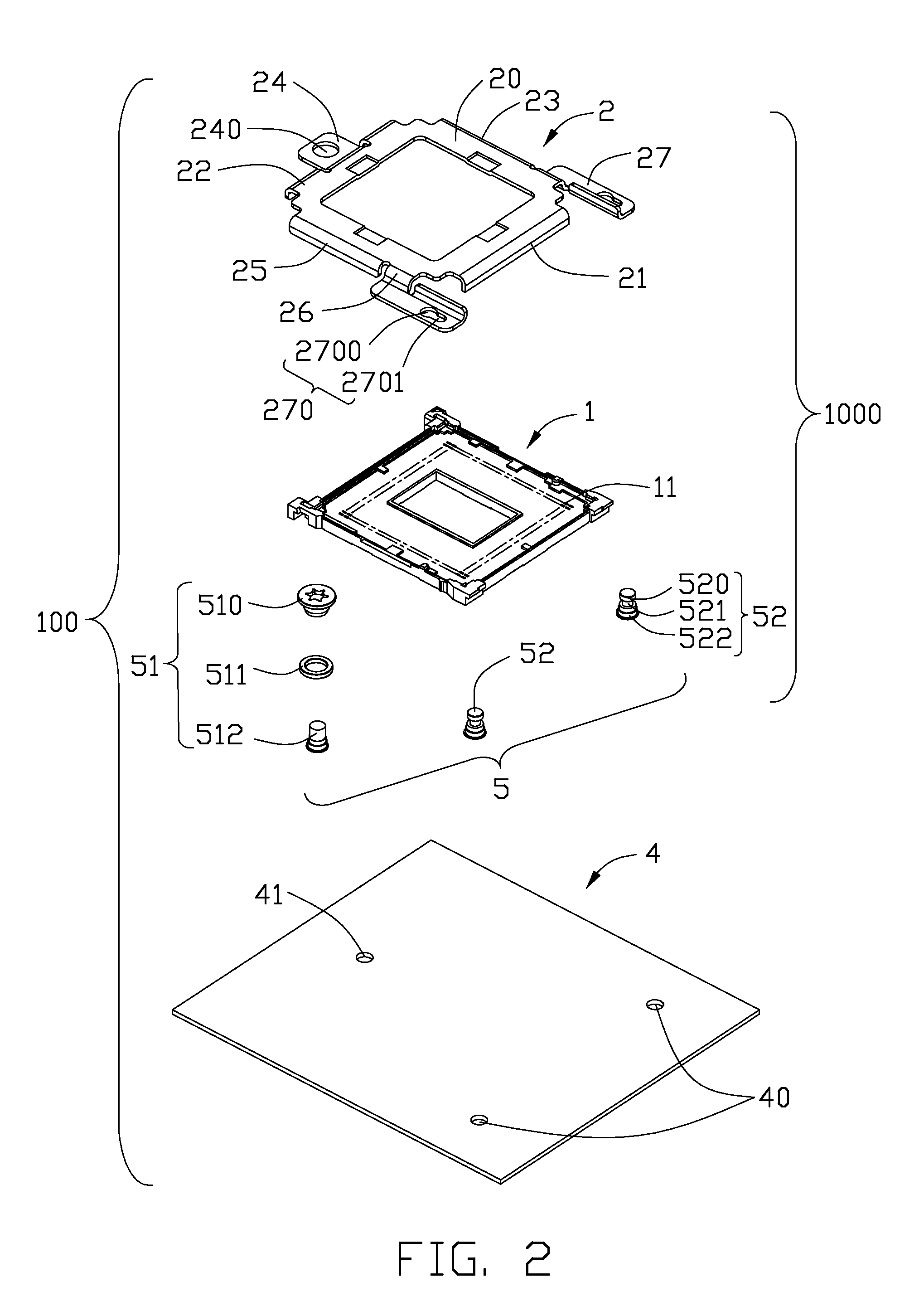
[0016]Referring to FIGS. 1-6, an electrical connector assembly 100 according to the present invention comprises a printed circuit board 4 and a socket connector 1000 mounted onto the printed circuit board 4. The socket connector 1000 comprises an insulating housing 1 having a plurality of terminals (not show) received therein and a clip (not show) mounted to the printed circuit board 4. The clip (not show) includes a cover 2 located above the insulating housing 1 and a plurality of retention members 5 for securing the cover 2 to the printed circuit board 4.

[0017]The cover 2 comprises a base portion 20 and a plurality of first, second, third and fourth sidewalls 21, 22, 23, 25 bending downwardly from the base portion 20. The cover 2 also comprises a first tongue portion 24 extending from the first side 21 of the base portion 20. The first tongue portion 24 has a through hole 240. A pair of se...


PUM


Abstract

An electrical connector assembly includes a printed circuit board, a socket connector assembled on the printed circuit board and a chip module seating on the insulative socket. The socket connector assembly has an insulating socket having a plurality of terminals received therein, a cover located on the insulating housing and three retention members secured to the printed circuit board and mating with the cover. The cover is attached to two of the retention members and capable of linear and rotational movements with regarding to said retention members so that the cover presses the chip module and is secured by another retention member.

Description

BACKGROUND OF THE INVENTION[0001]1. Field of the Invention[0002]The present invention relates to an individual loading mechanism (ILM), and more particularly an ILM with simplified locking mechanism facilitating reliable maneuver so as to press a CPU chip toward a socket connector mounted onto a printed circuit board.[0003]2. Description of the Prior Art[0004]An electrical connector electrically connecting a chip module to a printed circuit board is described in U.S. Pat. No. 7,628,634, issued to Yeh on Dec. 8, 2009. The electrical connector includes a socket body with a plurality of electrical contacts secured thereon, a metal load plate covering the socket body, a retention frame for securing the load plate on the printed circuit board, and a back plate. A fastener such as a first bolt is provided to engage with the load plate and fasten the load plate on the printed circuit board. The load plate is connected with and supported by the retention frame. The load plate includes a fra...

Claims


Application Information

Patent Timeline
Patent Type & Authority Patents(United States)
IPC IPC(8): H01R13/625
CPCH05K7/1053H05K7/12
Inventor YEH, CHENG-CHI
Owner HON HAI PRECISION IND CO LTD
Why Eureka
Try Eureka