Sensors and systems for detecting environmental conditions or changes

a technology of environmental conditions and sensors, applied in the field of sensors and systems for detecting environmental conditions or changes, can solve the problems of incontinence, difficulty or even impossible access, and difficulty in access, although possible or even simple, and achieve the effect of reducing the number of incontinence tests

Inactive Publication Date: 2013-08-06
BUNZA GEOFFREY J +1
View PDF122 Cites 35 Cited by
  • Summary
  • Abstract
  • Description
  • Claims
  • Application Information

AI Technical Summary

Problems solved by technology

However, such changes or conditions may occur in locations where access is difficult or even impossible, where access, although possible or even simple, is undesirable for any number of reasons, and / or where the environmental conditions or changes may be hazardous to humans and / or equipment.
For example, incontinence is a considerable problem in elder health care.
Elders often are immobile, and if these immobile elders become incontinent and lose control of the evacuative functions of urination or defecation and soil themselves, they may be unable to help themselves or seek help.
The urine or feces might stay in place long enough for the elder to develop sores, which can result in sickness, infection, and in the worse cases, even death.
This is an arduous and demeaning process, both for the caregiver and for the elder.

Method used


Image

  • Sensors and systems for detecting environmental conditions or changes
  • Sensors and systems for detecting environmental conditions or changes
  • Sensors and systems for detecting environmental conditions or changes

Examples


Embodiment Construction

[0037]The following description provides specific details for a thorough understanding of, and enabling description for, various examples of the technology. One skilled in the art will understand that the technology may be practiced without many of these details. In some instances, well-known structures and functions have not been shown or described in detail to avoid unnecessarily obscuring the description of the examples of the technology. It is intended that the terminology used in the description presented below be interpreted in its broadest reasonable manner, even though it is being used in conjunction with a detailed description of certain examples of the technology. Although certain terms may be emphasized below, any terminology intended to be interpreted in any restricted manner will be overtly and specifically defined as such in this Detailed Description section. Any headings used herein are provided for ease of reading and are not intended to limit the disclosure in any w...


PUM


Abstract

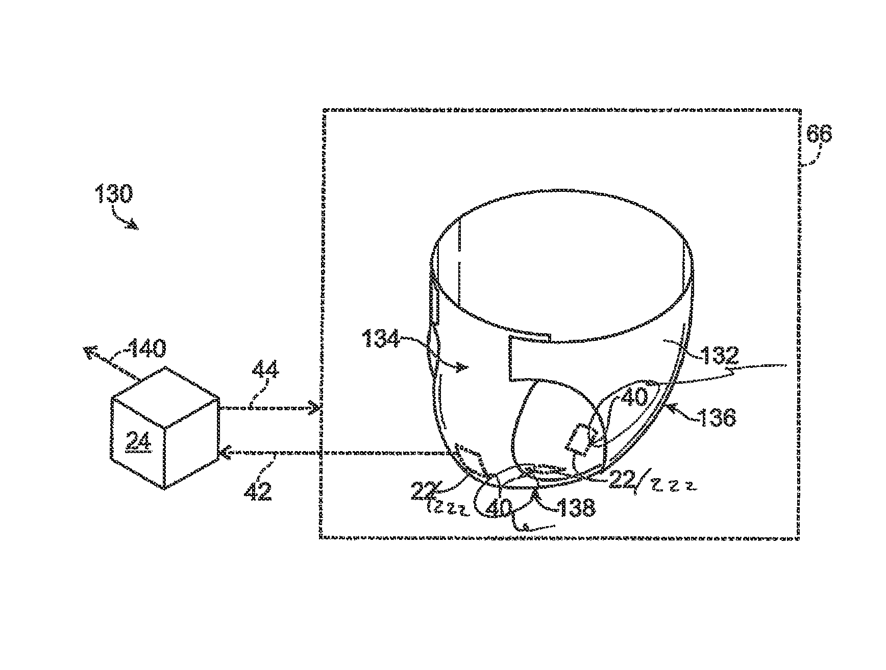
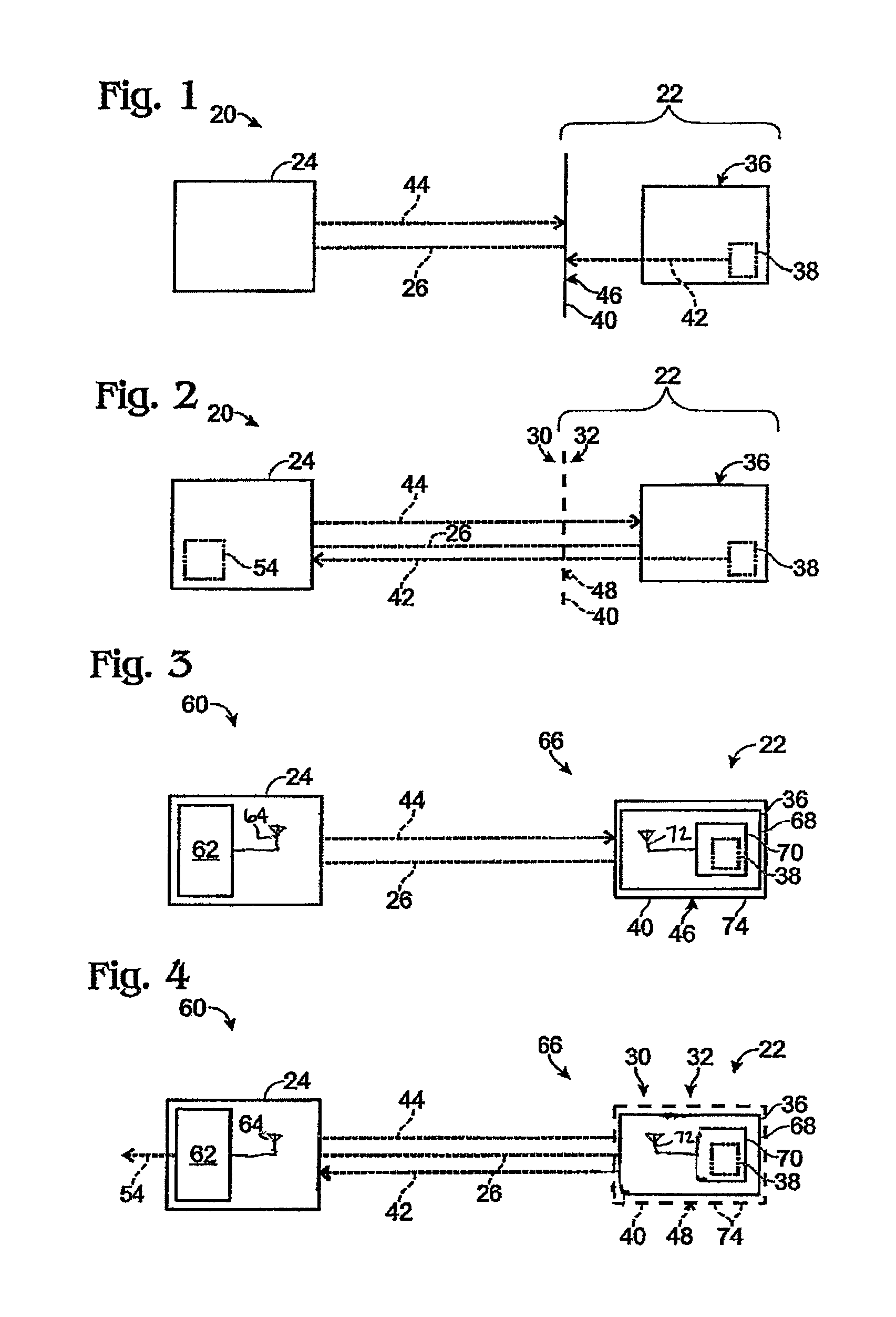
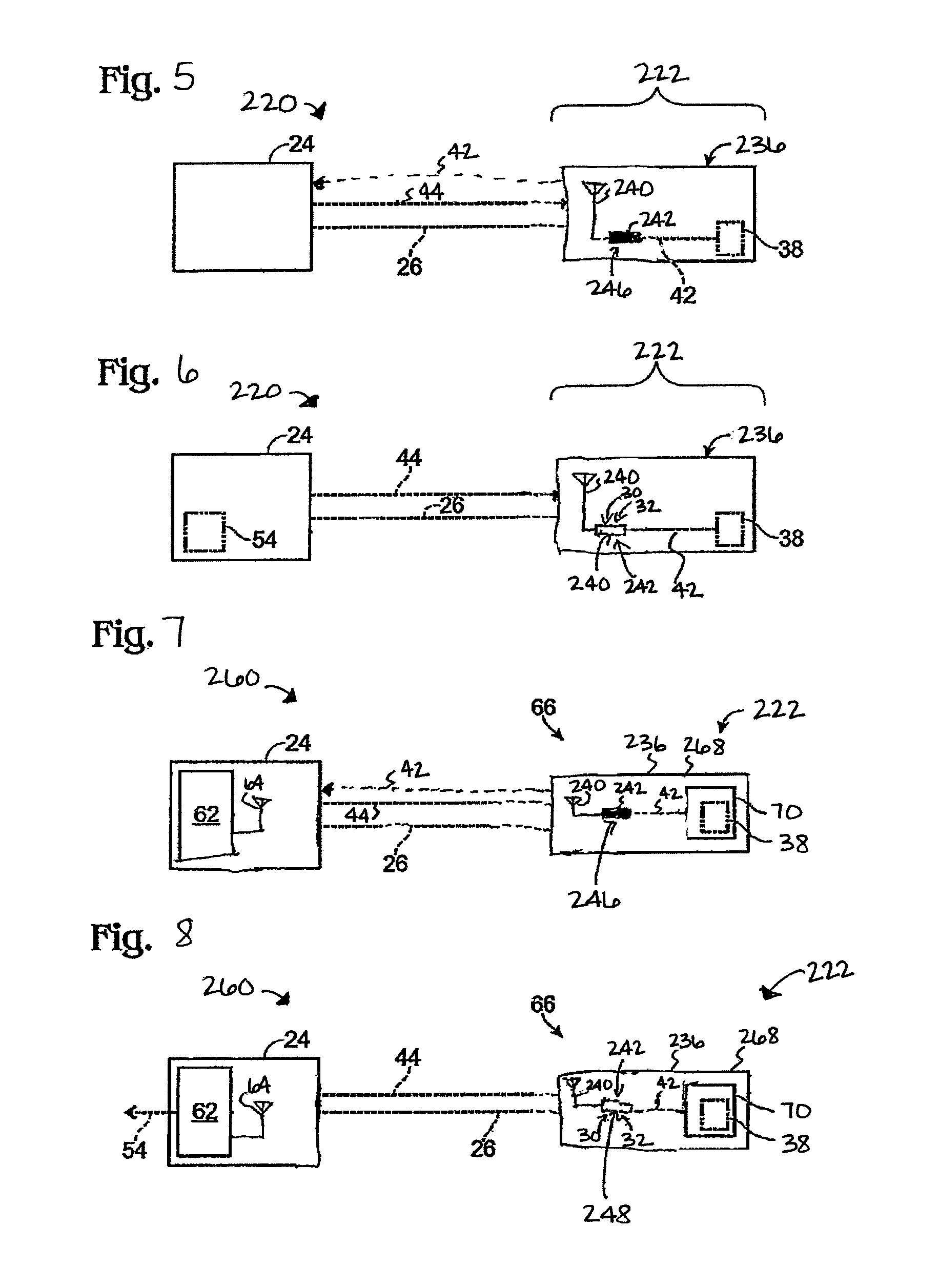
Sensors and systems for detecting predetermined environmental conditions or changes may include a device capable of providing information. The device may include either a shield or reconfigurable antenna. For example, in a first condition, a shield is configured to prevent communications with the device and, in a second condition, the shield is configured to enable communications with the device. Alternately, in a first condition, a reconfigurable antenna is configured to enable communications with the device and in a second condition the reconfigurable antenna is configured to prevent communications with the device. The shield or reconfigurable antenna may be configured to transition from first conditions to second conditions upon exposure to a predetermined environmental condition or change.

Description

CROSS REFERENCE TO RELATED APPLICATIONS[0001]This application is a continuation-in-part of U.S. patent application Ser. No. 12 / 902,115, filed Oct. 11, 2010, which is a continuation of U.S. patent application Ser. No. 11 / 615,313, filed Dec. 22, 2006 (now U.S. Pat. No. 7,812,731, issued Oct. 12, 2010). Each of these above-listed applications is hereby incorporated by reference.BACKGROUND OF THE DISCLOSURE[0002]The need to detect environmental conditions or changes arises in many situations. For example, solid materials or liquids may be introduced into or collect within an environment, parts or components of a system may wear down or out, or the temperature, pressure, chemical composition, atmosphere and / or some other environmental condition may change. Regardless of whether such changes or conditions may be beneficial, benign, harmful, desirable and / or undesirable, an indication of the change or condition may be useful. However, such changes or conditions may occur in locations where...

Claims


Application Information

Patent Timeline
Patent Type & Authority Patents(United States)
IPC IPC(8): G08B23/00
CPCA61B5/202A61B5/6808A61F5/48A61F13/42
Inventor BUNZA, GEOFFREY J.HUDNUT, STEVEN W.
Owner BUNZA GEOFFREY J
Why Eureka
Try Eureka