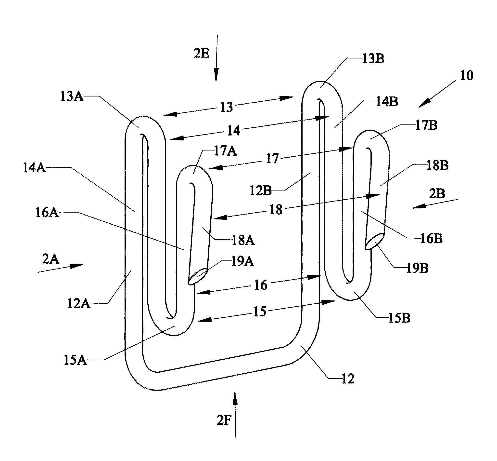
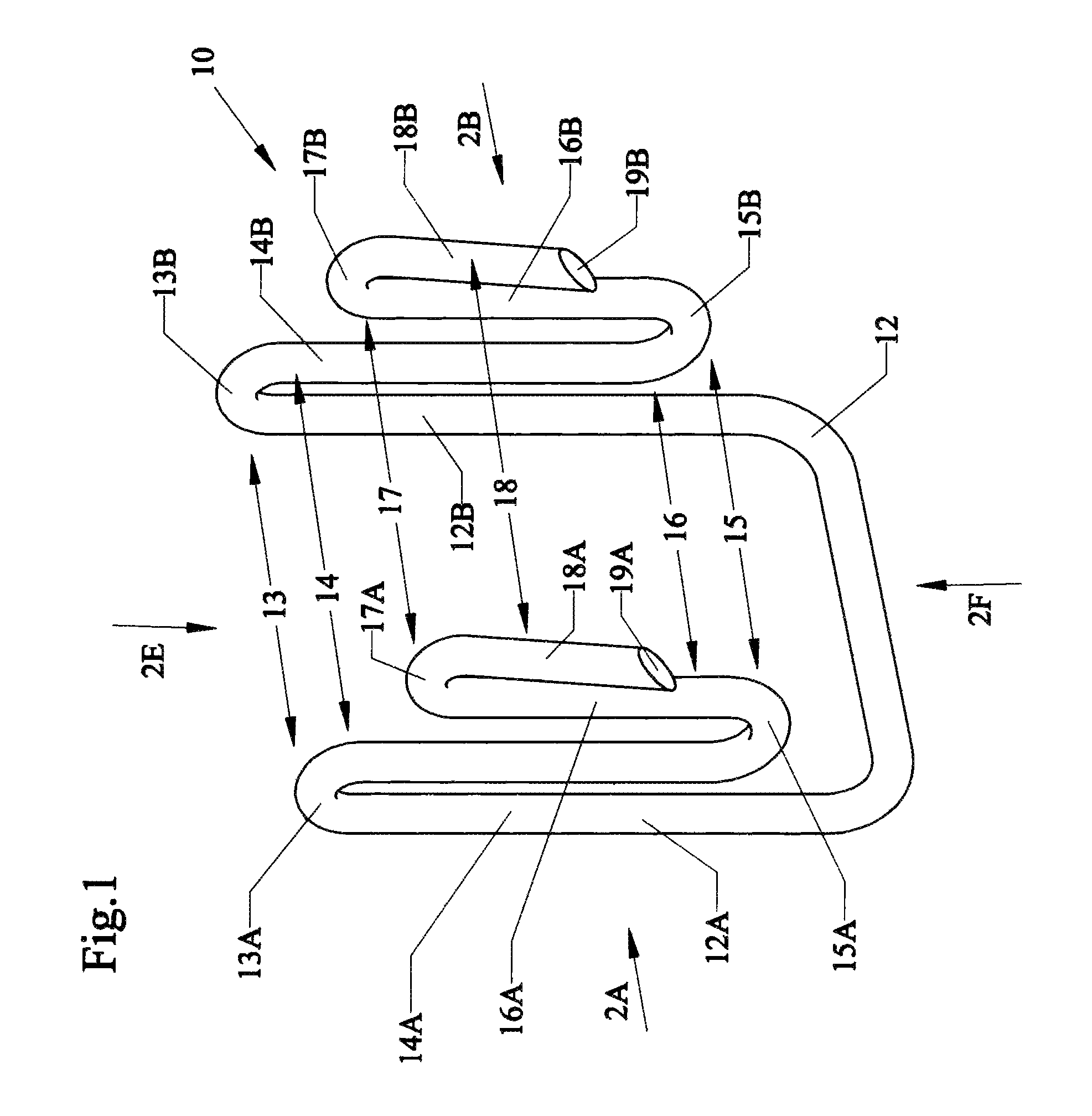
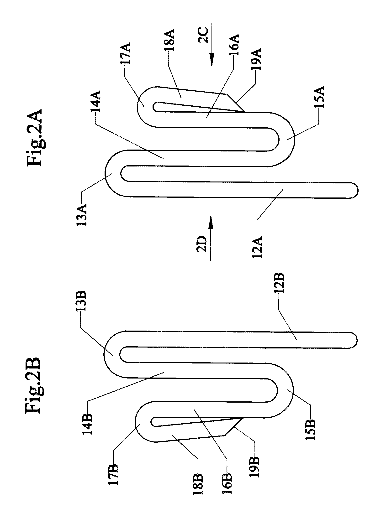
Adjustable line clip holder

a line clip and adjustable technology, applied in the field of clips, can solve the problems of patients' discomfort, lack of necessary support for relieving the pressure of skin, face, neck, etc., and achieve the effects of reducing the weight and pressure, reducing the pain of pulling the cannula from the patient's ears, and reducing the pain of pulling and yanking the lines on the ears

Inactive Publication Date: 2013-08-13
GRAY DEBORAH B
View PDF36 Cites 17 Cited by
  • Summary
  • Abstract
  • Description
  • Claims
  • Application Information

AI Technical Summary

Benefits of technology

[0018]A fifth objective of the present invention is to provide clip holders and methods of holding and supporting medical oxygen lines to patients so the patients can perform daily living activities with ease, without having to fight the oxygen line itself.
[0026]A thirteenth objective of the present invention is to provide clip holders and methods of holding and supporting medical oxygen lines to patients with ear supported cannulas, to safely and comfortably secure the lines allow for the patient to get in and out of vehicles (cars and like) during the day or night, and eliminate any cumbersome or burdensome difficulties while using the lines.

Problems solved by technology

However, the extensive use of a nasal cannula often irritates and causes discomfort to the patient.
The current nasal cannula apparatuses fail to provide necessary support in relieving the pressure of the cannula from the patient's ears, face, neck, and skin.
As a result, discomfort above and behind the patient's ears is a common occurrence.
Often the discomfort can start off with a simple redness and progress to sores or ulcerations above the ears due to constant rubbing of the tubing against the skin.
An additional problem occurs with moving patients.
Since a longer cannula is required for a freely moving patient, the additional weight from the longer cannula causes a substantial increase in pressure against the skin and areas that support and hold the cannula.
Further, the combination of the moving patient and long cannula can often cause the cannula to snag on furniture or other objects located around the patient.
However, the patient constantly having to hold the cannula while they move about will limit the patient to only being able to have use of one free hand during the day.
The displacement and pulling action can aggravate irritations and / or soreness associated with the use of the cannula.
Also, if the tubular branches of a nasal cannula are separated from the patient's ears, the nostril orifices can move out of contact with the patient's nostrils and render the cannula ineffective for its intended use and uncomfortable to the patient.
However, by attaching the cannula to eyeglasses or to a skull cap is that the patient cannot comfortably wear the eyeglasses or the skull cap when sleeping.
However, strap-like devices are limited in that when the tubular branches are supported within the ends of the strap-like device, the tubular portions can shift lengthwise relative to the end of the device.
Further, a strap-like device does little to alleviate the problem of snagging and pulling of the cannula for the moving patient.
However, since the pads do not provide a means for controlling the tension and pressure created by a cannula, the pads do not eliminate all the discomfort associated with the use of a cannula.
Pads are sometimes placed over areas already irritated by the cannula, which can slow the healing process around that area.
Further, these pads must often be replaced, making them an expensive and inefficient technique for overcoming the discomfort caused by a cannula.
By placing the medical tube holder on a strip and not directly on the clip, such devices are less effective in alleviating the pressure generated by the cannula against the patient's skin and ears because the strip can bend under the weight of the cannula or when the cannula is snagged against an object.
Further, a restive sleeping patient can dislodge the cannula, or even the elongate strip, thus rendering the common clip ineffective for its intended purpose.
Such fasteners can be difficult to use and ineffective in relieving the pressure of the cannula from the ears.
Moreover, the adhesives can irritate skin making such devices undesirable for extended use.

Method used


Image

  • Adjustable line clip holder
  • Adjustable line clip holder
  • Adjustable line clip holder

Examples


Embodiment Construction

[0058]Before explaining the disclosed embodiments of the present invention in detail it is to be understood that the invention is not limited in its applications to the details of the particular arrangements shown since the invention is capable of other embodiments. Also, the terminology used herein is for the purpose of description and not of limitation.

[0059]A list of components will now be described.[0060]10. clip holder[0061]12. rear U-shaped base[0062]12A. left base leg[0063]12B. right base leg[0064]13. first bends (upper bends)[0065]13A. left upper first bend[0066]13B. right upper first bend[0067]14. first set of (downwardly) extending prongs[0068]14A. left first downwardly extending prong[0069]14B. right first downwardly extending prong[0070]15. second bends (lower bends)[0071]15A. left second lower bend[0072]15B. right second lower bend[0073]16. second set of (upwardly) extending prongs[0074]16A. left upwardly second extending prong[0075]16B. right upwardly second extending ...


PUM


Abstract

Clips, devices, apparatus and methods of holding and supporting different diameter lines and conduits, such as medical oxygen air lines, earphone or headset wire lines, other types of wires, and power cords, and the like in a clip that can attach to clothing such as to pants, belts and pockets. The clip can include a rear U-shaped base and downwardly and upwardly protruding elongated members having different sets of upper and lower bends. The clip can be formed from a single vinyl coated wire line, that forms three sets of bends, each set having a different diameter. The lines and conduits can be securely held in different diameter sets of bends.

Description

[0001]This invention is a Continuation-In-Part of U.S. Design patent application Ser. No. 29 / 381,756 filed Dec. 22, 2010, now U.S. Design Pat. D639,937 and this invention claims the benefit of priority to U.S. Provisional Application Ser. No. 61 / 410,379 filed Nov. 5, 2010.FIELD OF INVENTION[0002]This invention relates to clips, and in particular to clips, devices, apparatus and methods of holding and supporting different diameter conduits, such as medical air lines, earphone or headset lines, wires, and power cords in a clip that can attach to clothing such as to pants, belts and pockets.BACKGROUND AND PRIOR ART[0003]Oxygen tubes are often used by a patients that require oxygen or other gases over long periods of time. The tubes generally require a cannula apparatus such as a nasal cannula generally includes an oxygen-carrying tube with two branches capable of being draped over the ears of a patient. Two tubular branches are usually joined together in front of the patient's face wit...

Claims


Application Information

Patent Timeline
Patent Type & Authority Patents(United States)
IPC IPC(8): A44B6/00
CPCA45F5/021A45F5/022F16B2/248Y10T24/1394A61M2209/088
Inventor GRAY, DEBORAH B.ALEXANDER, WILLIAM L.
Owner GRAY DEBORAH B
Why Eureka
Try Eureka