Tool assembly for a ram driven press responsive to the stroke of the ram driven press

a technology of ram driven press and tool assembly, which is applied in the direction of mechanical means, other manufacturing equipment/tools, printing, etc., can solve the problem of adding to the cost of components

Active Publication Date: 2013-08-13
WILSON TOOL INT
View PDF37 Cites 9 Cited by
  • Summary
  • Abstract
  • Description
  • Claims
  • Application Information

AI Technical Summary

Problems solved by technology

However, additional features and/or added inspection, if not handled in a

Method used


Image

  • Tool assembly for a ram driven press responsive to the stroke of the ram driven press
  • Tool assembly for a ram driven press responsive to the stroke of the ram driven press
  • Tool assembly for a ram driven press responsive to the stroke of the ram driven press

Examples


Embodiment Construction

[0028]The following detailed description is exemplary in nature and is not intended to limit the scope, applicability, or configuration of the invention in any way. Rather, the following description provides practical illustrations for implementing exemplary embodiments of the present invention. Constructions, materials, dimensions, and manufacturing processes suitable for making embodiments of the present are known to those of skill in the field of the invention. Those skilled in the art will recognize that many of the examples provided have suitable alternatives that can be utilized.

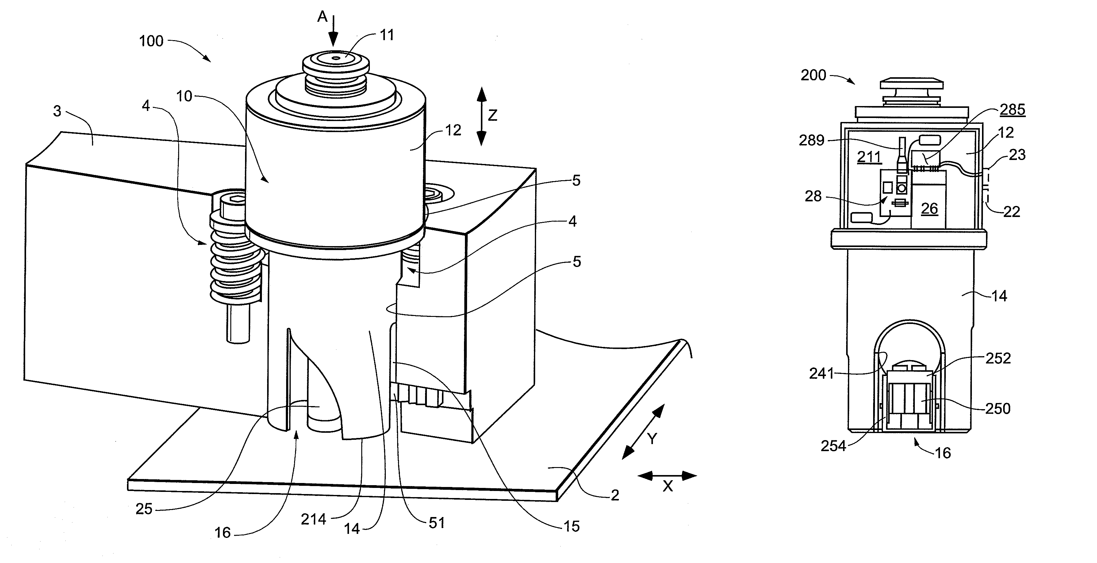
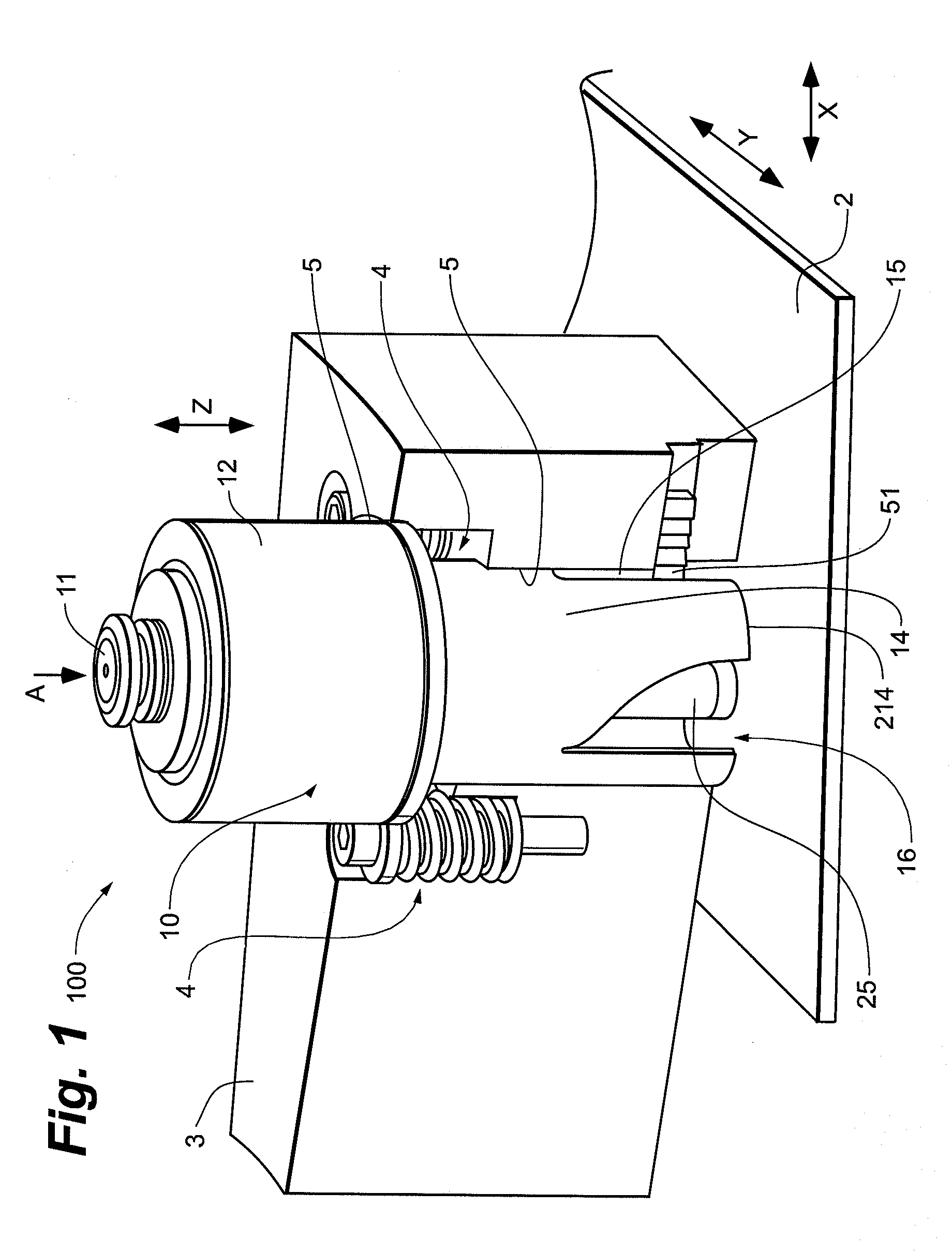
[0029]FIG. 1 is a perspective view of a tool assembly 100, according to some embodiments of the present invention, assembled into a portion of a press. FIG. 1 presents a segment of a mounting assembly, or upper turret 3, cut-away along a bore 5 thereof, in order to illustrate a mounting of tool assembly 100 therein for performing an operation on a sheet workpiece 2. FIG. 1 illustrates tool assembly 100...


PUM

PropertyMeasurementUnit
Poweraaaaaaaaaa
Energyaaaaaaaaaa
Proximity effectaaaaaaaaaa

Abstract

Assemblies and methods for processing a workpiece in a ram-driven press employ an active tool contained by a housing that is interchangeable with a passive forming tool assembly in a mounting assembly of the press. The active tool includes a microprocessor and a functional head coupled to the microprocessor. Some assemblies including the active tool include a switch for activating the functional head; the switch may be mounted to the housing such that, when the housing is mounted in the mounting assembly of the press, the switch is triggered by movement of the housing in response to the ram stroke of the press.

Description

[0001]This application claims priority to U.S. Application Ser. No. 60 / 914,468, filed Apr. 27, 2007, which is hereby incorporated by reference, in its entirety, herein.TECHNICAL FIELD[0002]The present invention pertains to assemblies and methods for processing work pieces and more particularly to assemblies and methods employed by ram-driven presses.BACKGROUND[0003]Ram-driven presses, for example, punch presses, are well known in the art. Punch presses are typically configured to hold a plurality of tools for forming a variety of shapes and sizes of indentations and / or holes in sheet workpieces, for example, sheet metal. Tools of this sort commonly include a punch and die; when a punch and corresponding die are mounted in a press and located in a working position of the press, beneath the ram (in some cases, coupled directly to the ram), the punch is driven, according to a pre-programmed ram stroke, to form an indentation or a hole through a sheet workpiece which has been located be...

Claims


Application Information

Patent Timeline
IPC IPC(8): B23P23/04
CPCB21D28/002B21D28/12B21D28/26B23B43/00B23G3/005B41J3/413B30B9/00B21D21/00Y10T483/13Y10T29/49897Y10T29/5155Y10T29/49995Y10T29/5128B21D35/001B21D37/00B23P23/04B41J2/01B23K26/38G01B7/102G01B7/012G01B5/012G03B19/00B23C7/00B21D28/02B21D28/125B23Q2003/15586B23Q5/28B41J3/445B41J2/17503
Inventor LEE, BRIAN J.MIKA, TIMOTHY J.
Owner WILSON TOOL INT
Why Eureka
Try Eureka