Portable, lightweight mount for a satellite antenna system

a satellite antenna and lightweight technology, applied in the direction of machine supports, collapsible antennas, other domestic objects, etc., to achieve the effect of strong and stable support, easy and quick adjustmen

Inactive Publication Date: 2013-08-13
WINEGARD
View PDF28 Cites 28 Cited by
  • Summary
  • Abstract
  • Description
  • Claims
  • Application Information

AI Technical Summary

Benefits of technology

[0009]The present invention involves a mount for mobile electronic devices such as a satellite dish antenna system. The mount includes a tripod and an elongated post member supported on it by a universal joint or pivot mechanism. The post member extends along a longitudinal axis and the pivot mechanism allows the post member to be moved about two, substantially perpendicular pivotal axes relative to the tripod to align the axis of the post member with the vertical. Once the longitudinal axis of the post member is aligned vertically, the alignment system of the attachable satellite dish will then have a proper reference from which to aim or direct the dish (e.g., azimuth and elevation) for best reception and transmission. The mount can be used on rough and inclined surfaces wherein the post member can be easily and quickly adjusted relative to the tripod up to about plus / minus 30 degrees. The mount includes an arrangement of cables extending between the tripod legs and adjustable straps extending between each tripod leg and the post member to provide a very strong and stable support for the satellite dish antenna system that is attachable to the upper end of the vertically aligned post member.

Problems solved by technology

They also need to be able to be carried and quickly deployed in a short amount of time by one person on surfaces that are often very rough and uneven.

Method used


Image

  • Portable, lightweight mount for a satellite antenna system
  • Portable, lightweight mount for a satellite antenna system
  • Portable, lightweight mount for a satellite antenna system

Examples


Embodiment Construction

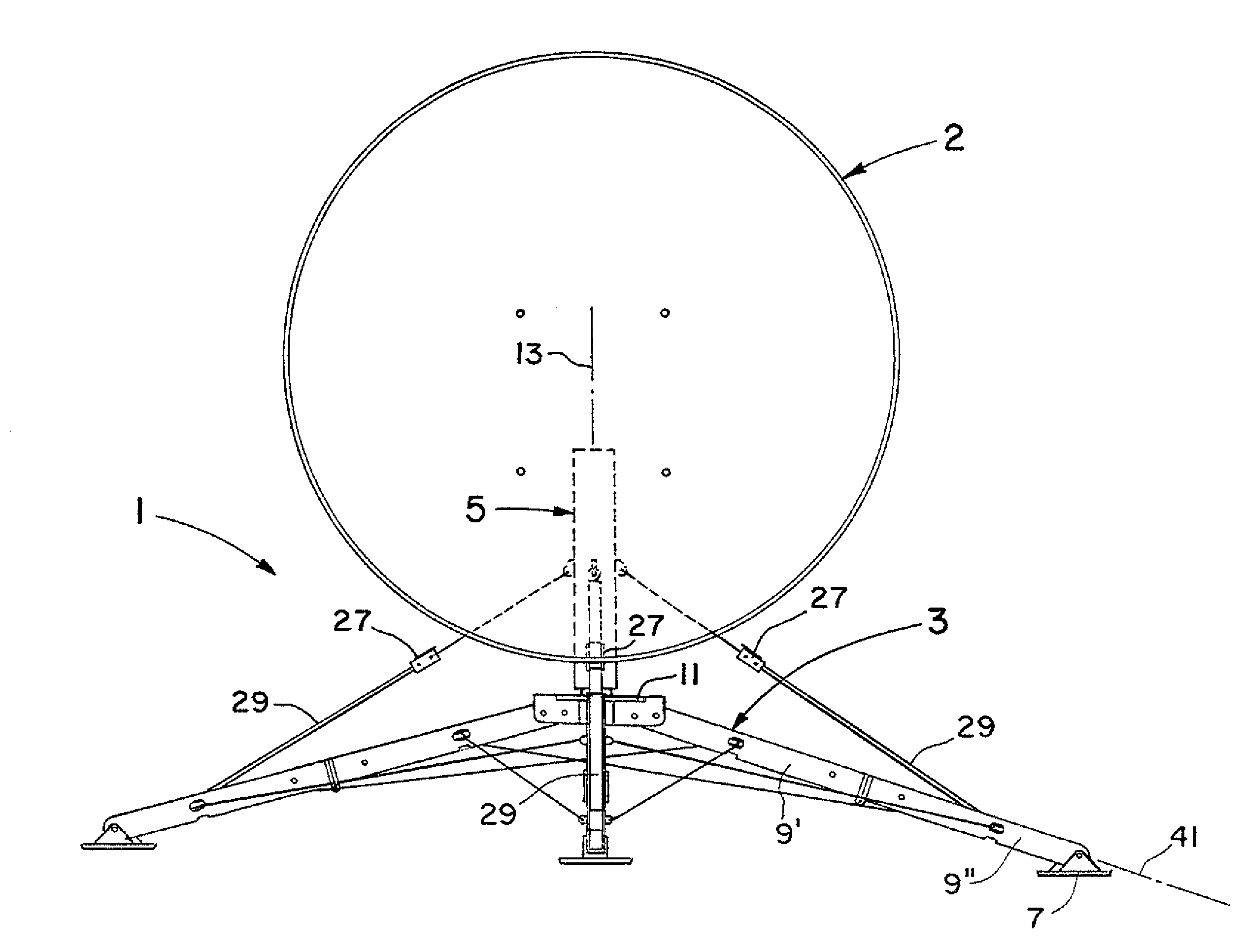
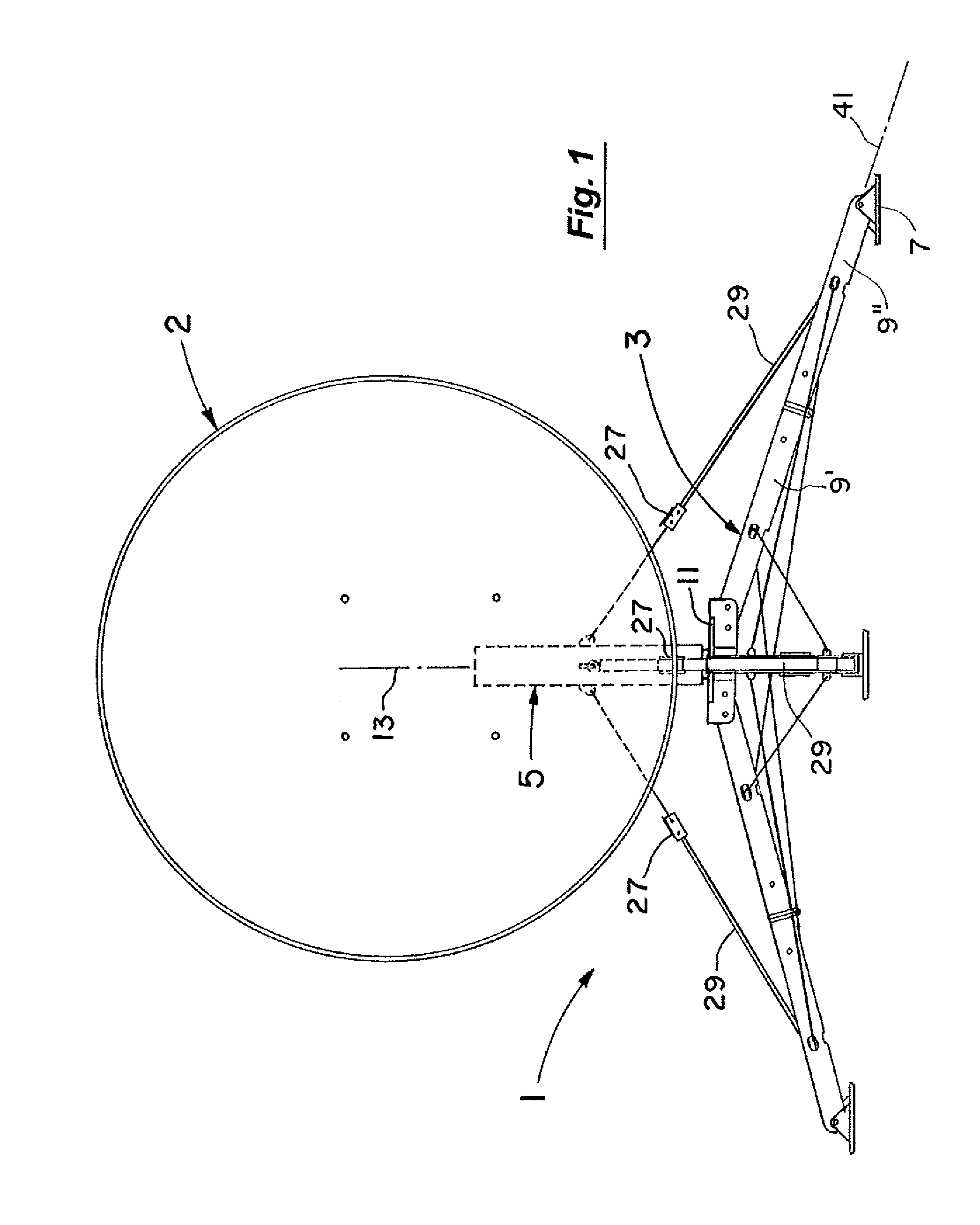
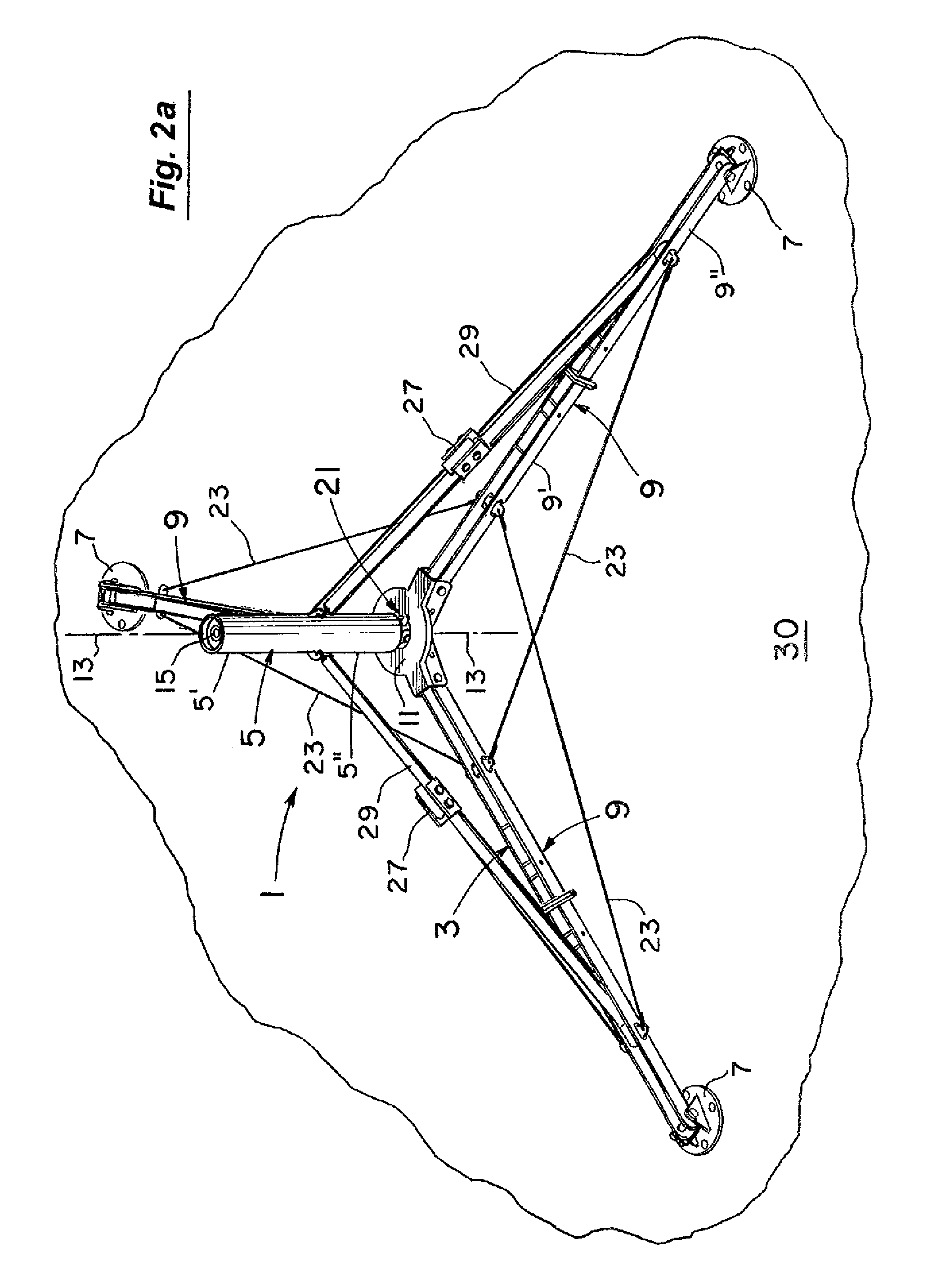
[0023]FIG. 1 illustrates the mount 1 of the present invention in use supporting a satellite dish system having a dish antenna 2. The mount 1 includes a tripod 3 (see also FIGS. 2a and 2b) and an elongated post member 5 which is removably supported on the tripod 3. The tripod 3 itself has three foot pads 7 (see FIGS. 2a and 2b), three elongated support legs 9, and a central member 11. The elongated post member 5 in use is then supported on the central member 11 of the tripod 3 as shown. The elongated post member 5 extends along a longitudinal axis 13 as in FIGS. 1 and 2a between upper and lower sections 5′ and 5″ (FIG. 2a). The upper section 5′ has a built-in bubble level at 15 (FIG. 2a) and the lower section 5″ has a universal joint or pivot mechanism at 21. As explained in more detail below, the universal joint or pivot mechanism at 21 allows the post member 5 to be pivoted relative to the central member 11 of the tripod 3 about two, substantially perpendicular axes to virtually an...


PUM


Abstract

A mount for mobile electronic devices such as a satellite dish antenna system. The mount includes a tripod and an elongated post member supported on it by a universal joint or pivot mechanism. The post member extends along a longitudinal axis and the pivot mechanism allows the post member to be moved about two, substantially perpendicular pivotal axes relative to the tripod to align the longitudinal axis of the post member with the vertical. Once the axis of the post member is aligned vertically, the alignment system of the attachable satellite dish will then have a proper reference from which to aim or direct the dish (e.g., azimuth and elevation) for best reception and transmission. The mount includes an arrangement of cables extending between the tripod legs and adjustable straps extending between each tripod leg and the post member to provide a very strong and stable support for the satellite dish antenna system that is attachable to the upper end of the vertically aligned post member. The tripod is designed to be foldable into a compact configuration for easy transport and storage with each tripod leg folded onto itself and positioned under a central member of the tripod. The folding and unfolding of the tripod and the alignment of the post member to the vertical on it can all be done by one person without the need for any tools.

Description

RELATED PATENT APPLICATIONS[0001]This application claims the benefit of U.S. Provisional Patent Application Ser. No. 61 / 309,970 filed Mar. 3, 2010, which is incorporated herein by reference.BACKGROUND OF THE INVENTION[0002]1. Field of the Invention[0003]This invention relates to field of portable, lightweight mounts for mobile electronic devices such as satellite antenna systems and more particularly to the field of such mounts that can be easily assembled for use at a variety of rugged and remote locations and easily leveled on severe and uneven surfaces for use.[0004]2. Discussion of the Background[0005]Customers, especially business customers, continually require a lower cost, lightweight, and portable mount for mobile electronic devices such as automatic satellite acquisition antenna systems wherein the mount can be easily assembled and disassembled at remote locations. Such antenna systems are commonly referred to as “flyaway” due to their lightweight and compactness during tra...

Claims


Application Information

Patent Timeline
Patent Type & Authority Patents(United States)
IPC IPC(8): F16M11/38
CPCF16M11/04H01Q1/12H01Q1/1235
Inventor CONRAD, TIMOTHY JOHN
Owner WINEGARD
Why Eureka
Try Eureka