Insert for implantable electrode

a technology of implantable electrodes and inserts, which is applied in the direction of internal electrodes, spinal electrodes, therapy, etc., can solve the problems of labor-intensive, time-consuming, labor-intensive, and labor-intensive fabrication of such electrodes, and achieve the effect of facilitating manufacturing

Inactive Publication Date: 2013-08-13
LIVANOVA USA INC
View PDF31 Cites 2 Cited by
  • Summary
  • Abstract
  • Description
  • Claims
  • Application Information

AI Technical Summary

Benefits of technology

[0004]In accordance with another embodiment, a method of making an electrode comprises providing a first hollow body member having a first keyed outer surface, providing a first conductor and a first electrode provided on the first conductor, and positioning the first electrode in a first electrode receptacle formed in the first hollow body member. The method also comprises inserting the first conductor through a first through hole in a tubing such that the first keyed surface is substantially aligned with a first corresponding surface of the tubing to thereby orient the first electrode in a predetermined orientation with respect to the tubing.

Problems solved by technology

Such electrodes are typically fragile and should be handled carefully by the implantation surgeon when coupling the electrode to the relevant tissue to be stimulated.
Fabrication of such electrodes is a labor-intensive, time-consuming process.
Creating the proper relative radial and linear placement of the electrodes relative to one another on the lead during manufacturing is a painstaking and time-consuming process.

Method used


Image

  • Insert for implantable electrode
  • Insert for implantable electrode
  • Insert for implantable electrode

Examples


Embodiment Construction

[0030]The following discussion is directed to various embodiments of the invention. Although one or more of these embodiments may be preferred, the embodiments disclosed should not be interpreted, or otherwise used, as limiting the scope of the disclosure, including the claims. In addition, one skilled in the art will understand that the following description has broad application, and that the discussion of any embodiment is meant only to be exemplary of that embodiment, and is not intended to intimate that the scope of the disclosure, including the claims, is limited to that embodiment. Any numerical dimensions provided herein are merely exemplary and do not limit the scope of this disclosure or the claims that follow.

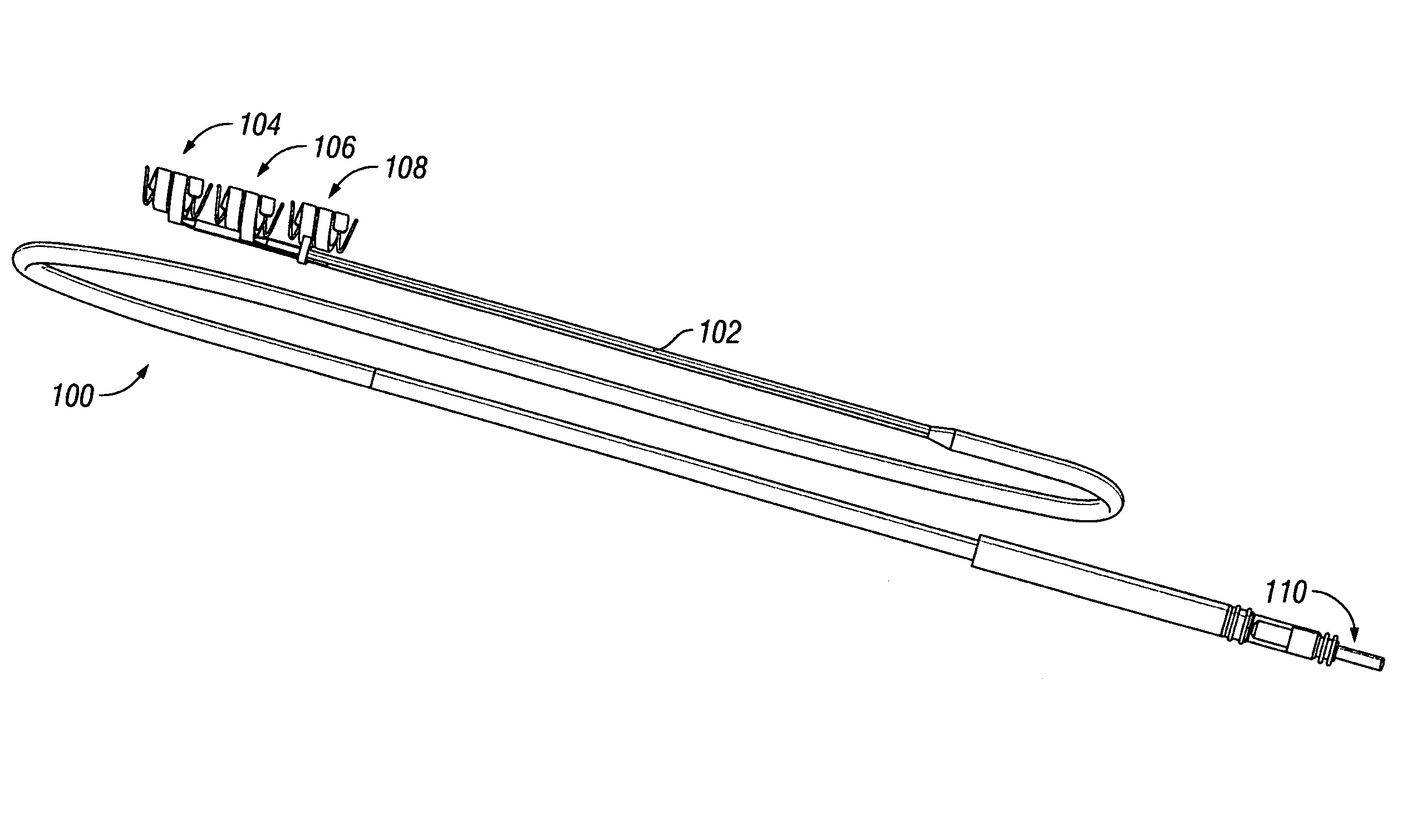
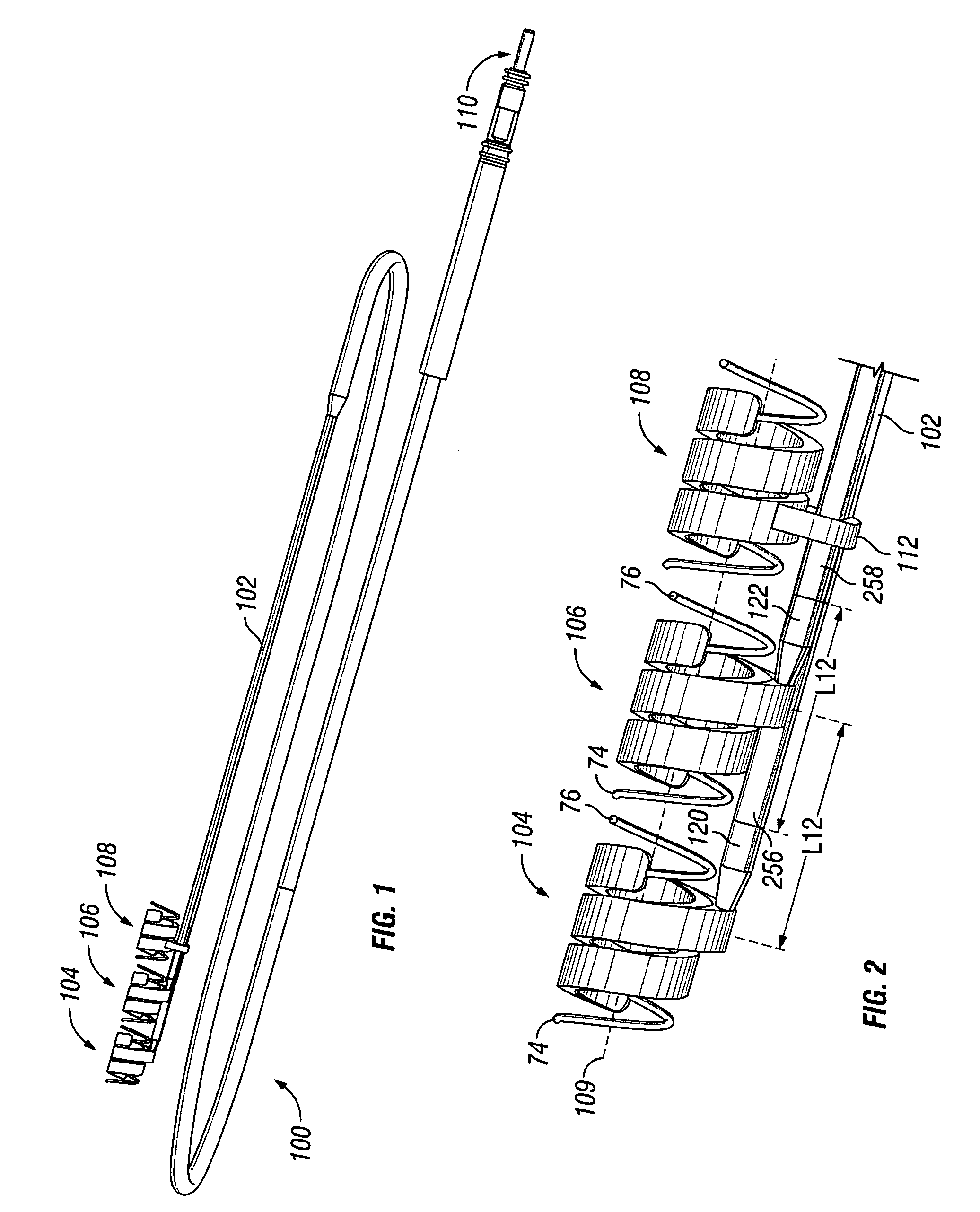
[0031]FIG. 1 depicts a complete implantable lead assembly 100 in accordance with a preferred embodiment of the invention. As shown, the lead assembly 100 comprises conductive electrodes 104 and 106, a lead body 102 comprising a coil and an outer body tubing or insula...


PUM


Abstract

A lead assembly comprises an outer body tubing, first and second conductors, and first and second tubing insert members. The outer body tubing comprises at least two longitudinal outer body tubing portions, each such portion comprising a through-hole and each portion comprising a keyed surface having a predetermined shape. Each of the tubing insert members receives a conductor and comprises a surface that substantially matches the predetermined shape of the keyed surface. When both of the conductors are inserted into corresponding longitudinal through-holes such that each of said first and second surfaces of the first and second hollow body members is substantially aligned with the keyed surface of a corresponding outer body tubing portion, electrodes formed on ends of the first and second conductors are encouraged to be substantially co-linear.

Description

BACKGROUND[0001]Many types of implantable medical devices, such as pacemakers, defibrillators, and vagus nerve stimulators, have leads connected to an electronics unit. The distal end of the lead typically comprises (or is coupled to) one or more conductive electrodes. Such electrodes are typically fragile and should be handled carefully by the implantation surgeon when coupling the electrode to the relevant tissue to be stimulated. Fabrication of such electrodes is a labor-intensive, time-consuming process. In some cases, a lead comprises two or more electrodes that preferably are arranged with a certain placement relative to each other. The relative placement involves both the distance separating the electrodes as well as the orientation on the lead of one electrode relative to the other. The proper spacing helps to ensure proper functioning of the associated implantable medical device. Proper orientation helps to ensure satisfactory coupling between the electrodes and the relevan...

Claims


Application Information

Patent Timeline
Patent Type & Authority Patents(United States)
IPC IPC(8): A61N1/05
CPCA61N1/0551A61N1/0556A61N1/0558
Inventor KOLLATSCHNY, SHAWN D.SCIACCA, JOSEPH J.
Owner LIVANOVA USA INC
Why Eureka
Try Eureka