Supercharge Your Innovation With Domain-Expert AI Agents!

Optimizing workflow engines

a workflow engine and workflow technology, applied in the field of information technology, can solve the problem that existing approaches are disadvantageously not taking into account dynamic information

Inactive Publication Date: 2013-08-13
INT BUSINESS MASCH CORP
View PDF20 Cites 12 Cited by
  • Summary
  • Abstract
  • Description
  • Claims
  • Application Information

AI Technical Summary

Benefits of technology

The invention provides techniques for optimizing workflow engines. A method involves merging a workflow to create a virtual graph, mapping nodes in the graph to physical nodes, and using a message passing scheme to implement a computation via the physical nodes. The techniques allow for more efficient and streamlined processing of data through a workflow system. A computer product and apparatus for carrying out the method are also described. The invention simplifies the way work is done, improves efficiency, and reduces the amount of data that needs to be processed.

Problems solved by technology

Secondly, users can also create workflows by changing existing workflows slightly.
Existing approaches disadvantageously do not take dynamic information into account.

Method used


Image

  • Optimizing workflow engines
  • Optimizing workflow engines
  • Optimizing workflow engines

Examples


Embodiment Construction

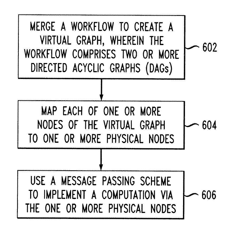
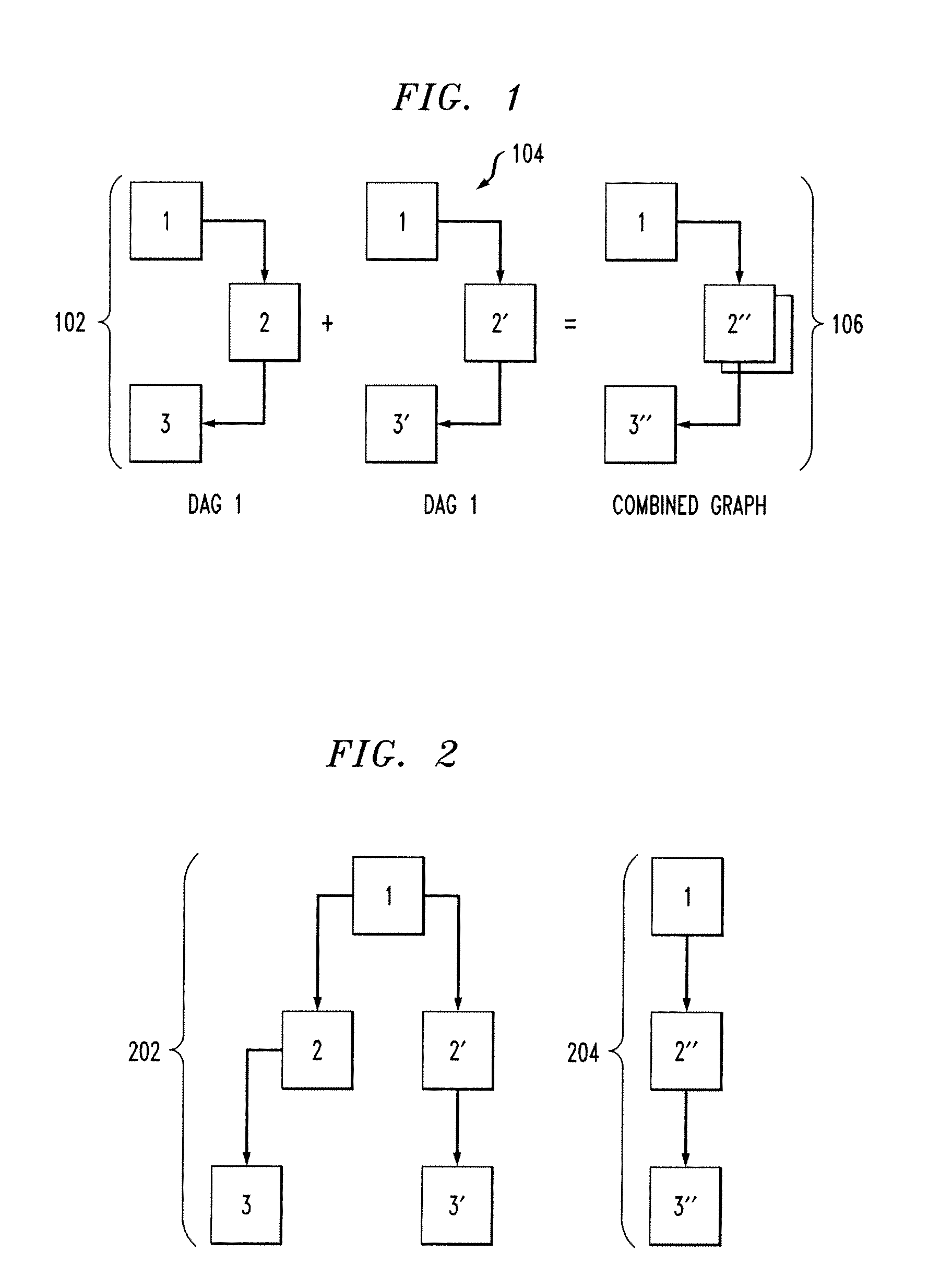
[0017]Principles of the invention include running a set of workflows on a cluster of processing elements. One or more embodiments of the invention include merging a set of workflow directed acyclic graphs (DAGs) into one large graph that minimizes the number of nodes statically. Also, each vertex can be mapped to a processing node.

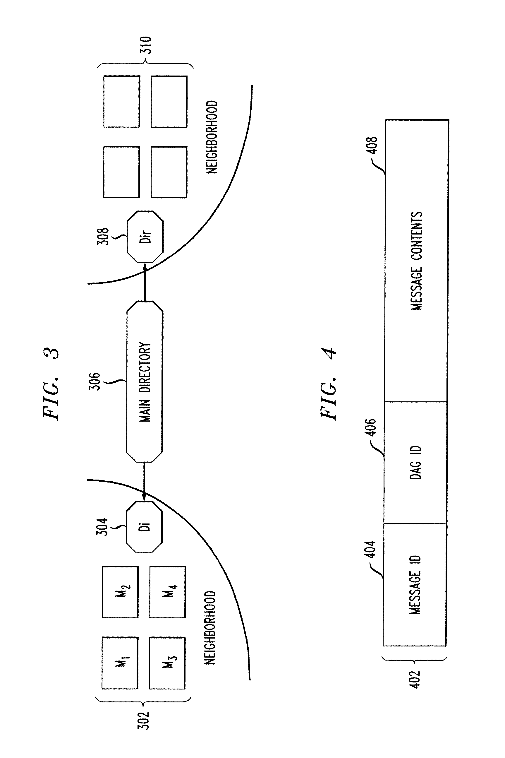
[0018]In contrast to existing approaches, one or more embodiments of the invention can include merging vertices even if they do not have the same predecessors and successors. The techniques detailed herein can include assigning vertices to one virtual node, and using a directory-based system in the virtual node directory to keep track of the different merging operations that have been done. Also, one or more embodiments of the invention include merging vertices to virtual nodes to reduce license uses, increase locality in caching-paging behavior, and decrease communication time.

[0019]Additionally, the techniques described herein include a practical system ...


PUM


Abstract

A system and computer program product for implementing a workflow include merging a workflow to create a virtual graph, wherein the workflow comprises two or more directed acyclic graphs (DAGs), mapping each of one or more nodes of the virtual graph to one or more physical nodes, and using a message passing scheme to implement a computation via the one or more physical nodes.

Description

FIELD OF THE INVENTION[0001]Embodiments of the invention generally relate to information technology, and, more particularly, to workflow engines.BACKGROUND OF THE INVENTION[0002]A workflow engine is a software system used to run a multitude of tasks. Each task is typically the invocation of an executable program. These tasks may have precedence relationships between them. Thus, the workflow may be looked upon as a graph, where each node represents a task to be performed, and an edge represents a precedence relationship. In a majority of cases, the workflow task graph can be acyclic.[0003]Typically, users run a set of workflows at one go. In this set, users can create copies of a workflow for different inputs. Secondly, users can also create workflows by changing existing workflows slightly. As such, it would be a sub-optimal choice to consider each workflow as a separate entity. To minimize computation in the workflow set and take advantage of the common structure, it would be desir...

Claims


Application Information

Patent Timeline
Patent Type & Authority Patents(United States)
IPC IPC(8): G06F3/00G06F9/44G06F9/45
CPCG06F9/5038
Inventor SAHA, DHRUBAJYOTISARANGI, SMRUTI R.
Owner INT BUSINESS MASCH CORP
Features
  • R&D
  • Intellectual Property
  • Life Sciences
  • Materials
  • Tech Scout
  • Unparalleled Data Quality
  • Higher Quality Content
  • 60% Fewer Hallucinations
Learn More