Method for Debugging a Business Process Flow

a business process and flow technology, applied in the field of information technology, can solve problems such as loss of productivity and downtime of production applications while debugging

Inactive Publication Date: 2007-11-29
INT BUSINESS MASCH CORP
View PDF14 Cites 46 Cited by
  • Summary
  • Abstract
  • Description
  • Claims
  • Application Information

AI Technical Summary

Problems solved by technology

Another drawback is that the production application is down while debugging.
This could mean loss of productivity.

Method used


Image

  • Method for Debugging a Business Process Flow
  • Method for Debugging a Business Process Flow
  • Method for Debugging a Business Process Flow

Examples


Embodiment Construction

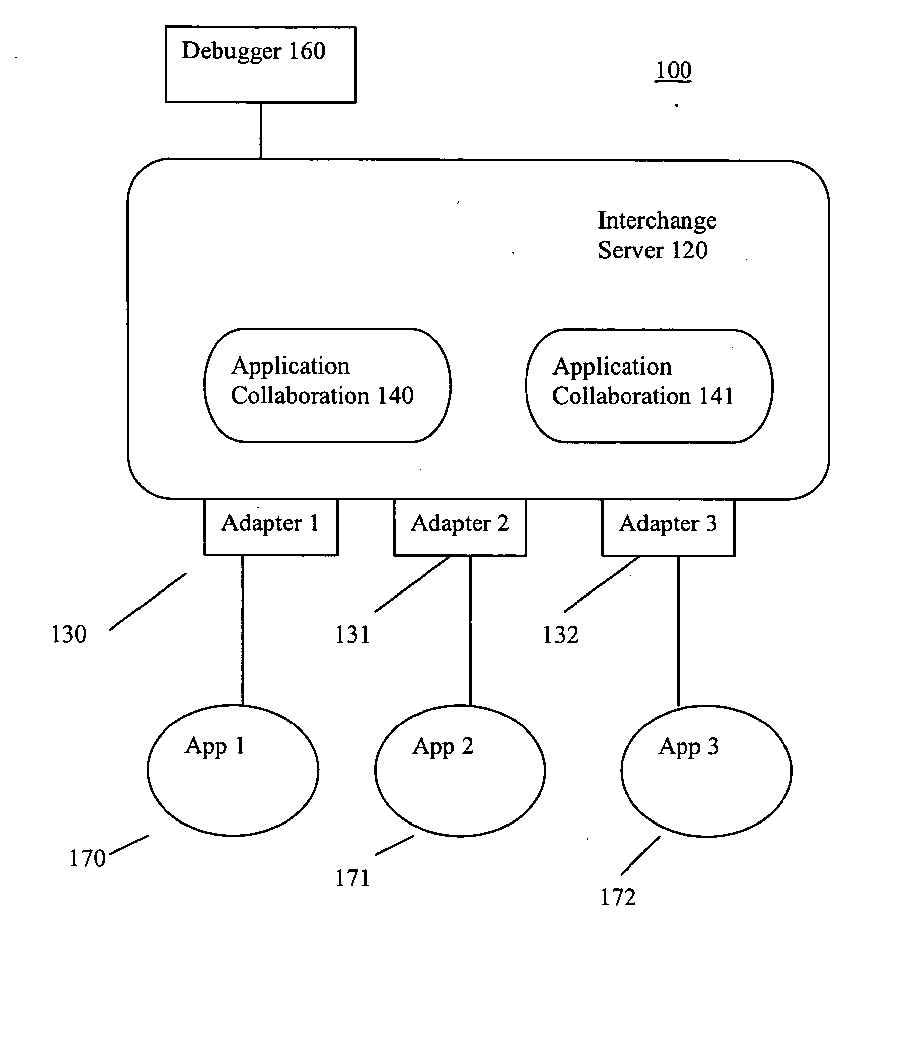
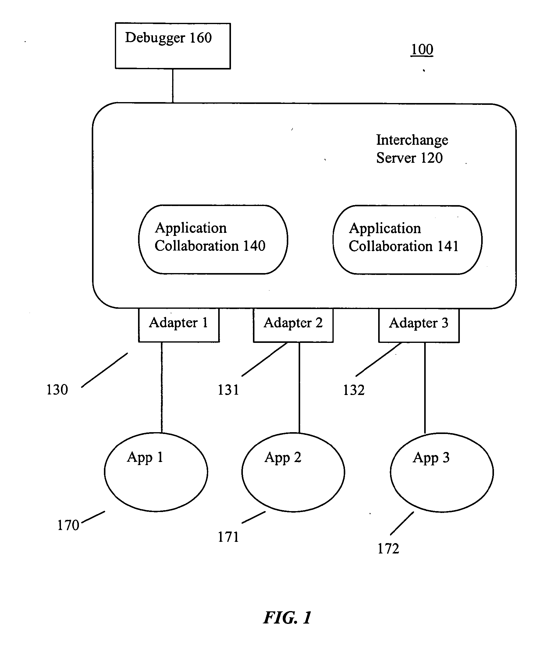
[0016] Referring to FIG. 1, there is shown a block diagram of a hub and spoke application integration system 100 that includes an interchange server 120 having one or more adapters (also known as connectors) 130, and one or more application collaboration modules 140, and a collaboration debugger 160 according to an embodiment of the invention. Coupled to each connector 130 is an application 170. A system such as the system 100 (without the debugger) is described in U.S. Pat. No. 6,223,585 the specification of which is hereby incorporated by reference.

[0017] The Interchange server 120 is a distributed application server that includes a workflow engine function and that provides an object oriented run-time platform for all components. It also provides mechanisms to manage, configure and control components and provides all of the reliability, availability, and serviceability features (the RAS features) found in a typical server environment. An object component can reside in any interc...


PUM


Abstract

A method for debugging a process in a workflow engine, wherein the process includes a plurality of activity points, includes steps of: attaching to a running business process being controlled by the workflow engine; initiating a debugging session; receiving a set of breakpoints to be inserted into designated points in the process; stopping the running of the process at one or more of the breakpoints; and presenting a user with information relating to where the process has stopped and the status of the process flow.

Description

CROSS-REFERENCE TO RELATED APPLICATIONS [0001] This application is a continuation of U.S. application Ser. No. 10 / 740,931, filed Aug. 11, 2005; said application incorporated by reference in its entirety as if fully set forth herein.STATEMENT REGARDING FEDERALLY SPONSORED-RESEARCH OR DEVELOPMENT [0002] None. INCORPORATION BY REFERENCE OF MATERIAL SUBMITTED ON A COMPACT DISC [0003] Not Applicable. FIELD OF THE INVENTION [0004] The invention disclosed broadly relates to the field of information technologies and more particularly relates to the field of debugging workflow programs. BACKGROUND OF THE INVENTION [0005] Workflow engines perform an automatic routing of documents to the users responsible for working on them. The documents may be physically moved over the network or maintained in a single database with the appropriate users given access to the data at the required times. [0006] A typical workflow engine has two components, design and runtime. The design component typically is ...

Claims


Application Information

Patent Timeline
Patent Type & Authority Applications(United States)
IPC IPC(8): G06Q10/00G05B19/418G06F15/02G06Q30/00G06F9/44
CPCG06F11/3664
Inventor MEI, XIAOCHUNMANAVALAN, RANGARAJAN S.GOOTY, SUBRAMANYAM A.
Owner INT BUSINESS MASCH CORP
Why Eureka
Try Eureka