Rolling device

a technology of rolling device and rolling bearing, which is applied in the direction of gearing, sliding contact bearings, hoisting equipment, etc., to achieve the effect of substantially preventing the leakage of noise generated within the rolling device, and improving the silencing

Active Publication Date: 2013-08-20
THK CO LTD
View PDF22 Cites 16 Cited by
  • Summary
  • Abstract
  • Description
  • Claims
  • Application Information

AI Technical Summary

Benefits of technology

[0031]According to the present invention, noise generated within the rolling device can be substantially prevented from leaking outward, so that in comparison with a conventional rolling device, a rolling device improved in silencing effect can be provided. Furthermore, according to the present invention, the rolling device improved in the silencing effect can be provided with cheap manufacturing cost.
[0032]Furthermore, since the end plate according to the present invention is formed by integrally constructing a plurality of different members, in comparison with a conventional technology in which these members are formed of independently different members, the end plate having small dimension or size can be manufactured, resulting in that the location spaces of the seal member and the packing member can be easily ensured, thus increasing freedom in design and realizing compact and light structure of the rolling device.
[0033]Still furthermore, in the conventional technology, it is necessary to perform position alignment working at the time of mounting the seal member to the rolling device. However, in the rolling device of the present invention, since the outer member (such as nut member) to which the end plate is provided is formed with high dimensional precision through a wire discharge working, it is allowed for the end plate to be disposed so as to accord with the positioning standard of the outer member which is worked with high precision. Therefore, according to the present invention, the end plate can be disposed without performing the position alignment working with respect to the outer member.
[0034]Still furthermore, according to the present invention, a play exists between the through hole and the connection member forming the integrating unit, and by providing such play between each through hole and each connection member, the positional movement of the seal member with respect to the end plate body becomes possible. According to such positional movement, it becomes possible for the seal member to achieve the self-aligning performance with respect to the inner member such as screw shaft, whereby the preferred contacting condition between the seal member and the inner member can be always automatically realized, and the rolling device having high sealing performance can be provided.

Problems solved by technology

However, the conventional technology provides a case such that when a number of rolling members circulate along the rolling passage, noises are caused by mutual contact of the rolling members or contact of the rolling member rolling in the outer member against a wall surface of the rolling passage.

Method used


Image

  • Rolling device
  • Rolling device
  • Rolling device

Examples


second embodiment

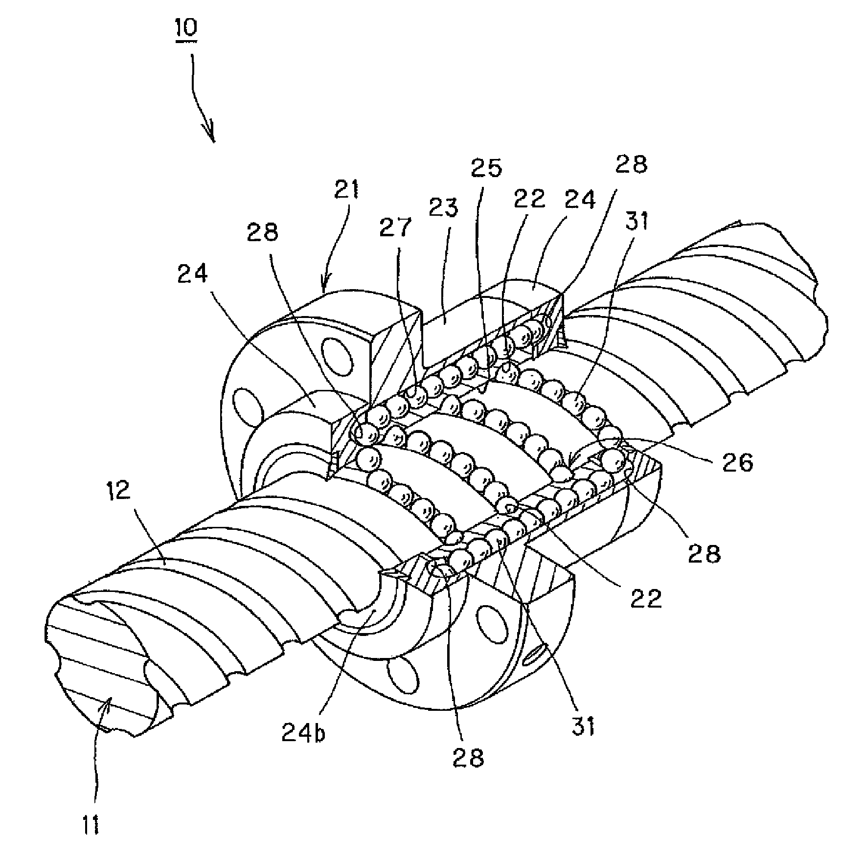
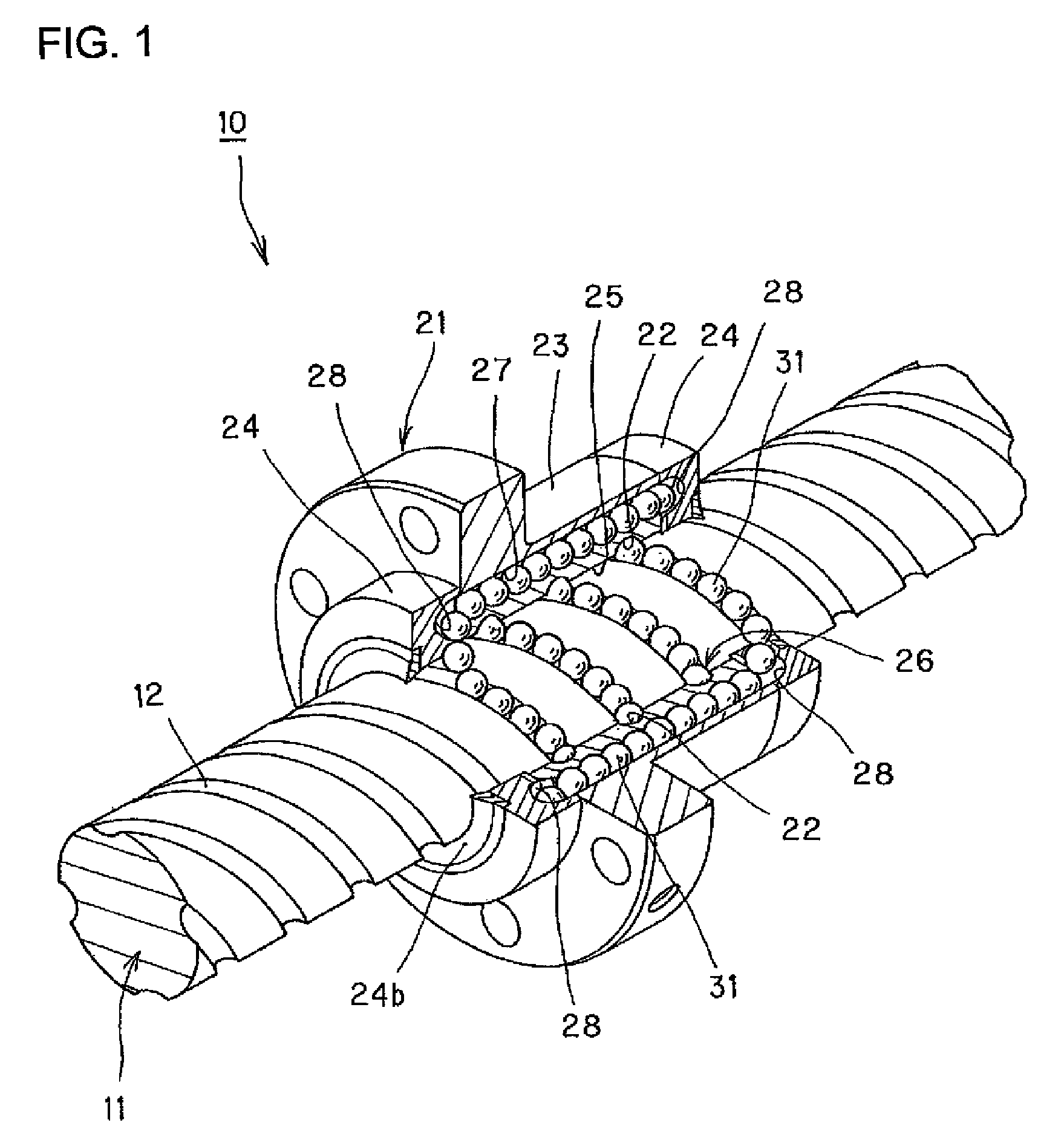
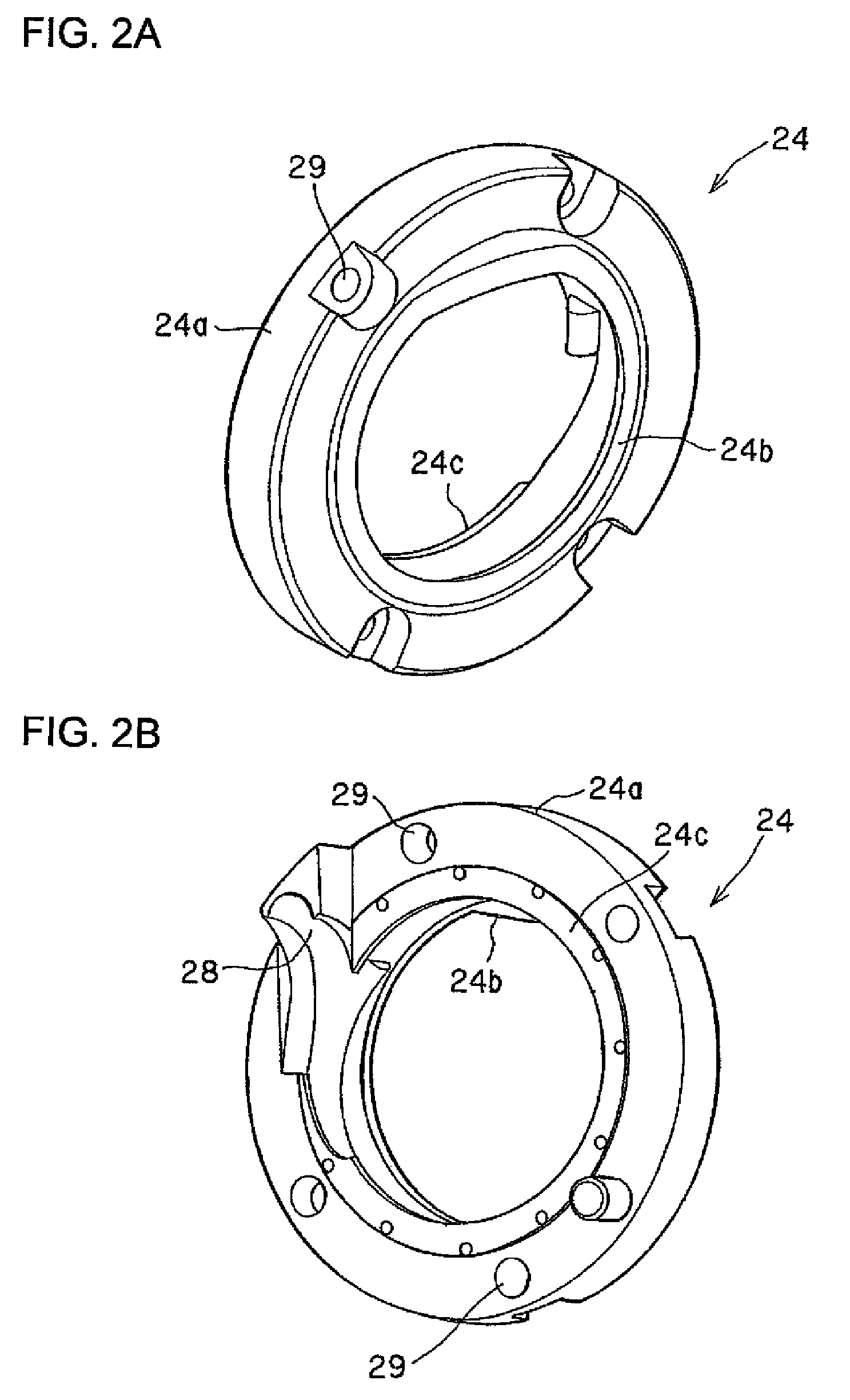
[0092]In the rolling device 10 according to the first embodiment mentioned above, there is explained, as an example, that a pair of end plates disposed to both the end portions of the nut body 23 are constructed as end caps 24 having direction changing passages 28. However, the present invention is not limitedly applied to so-called end cap-type ball screw device, and is applicable to various kinds or types of rolling devices. Accordingly, in the second embodiment described hereunder, an embodiment in which the present invention is applied to a ball screw device using no end cap 24. It is further to be noted that like or same reference numerals are added to members or portions corresponding to those of the first embodiment and the detailed explanations thereof are omitted herein.

[0093]FIG. 7 is a perspective view showing an outer configuration of a rolling device 40 according to the second embodiment, and the rolling device 40 of this embodiment is provided with the endless circulat...

third embodiment

[0106]In the above, although the embodiments of the ball screw devices of various types, to which the present invention is applied, are described hereinbefore, the present invention is not limited to the ball screw devices, and can be applied to every rolling device. Then, hereunder, in a third embodiment, an example in which the present invention is applied to a linear guide device will be explained.

[0107]FIG. 13 is a perspective view showing an outer configuration of a linear guide device 60 as a rolling device according to the third embodiment of the present invention.

[0108]The linear guide device 60 according to the third embodiment is provided with a track rail 61 as inner member and a movable block 71 as outer member mounted to the track rail 61 to be movable through balls, not shown, as rolling members.

[0109]The track rail 61 is a member having an extending scale in its longitudinal direction and having approximately rectangular cross section, and a loaded rolling groove 62 i...

fourth embodiment

[0121]In the third embodiment mentioned above, the present invention is applied to the linear guide device 60, and moreover, the present invention may be applied to a ball spline device.

[0122]For example, each of end caps 90 as end plates disposed both end portions of a spline outer cylinder of a ball spline device as explanatorily shown in FIG. 17 to FIG. 19 may be composed of an end cap body 90a shown in FIGS. 18A and 20A and a member formed of elastomer shown in FIGS. 18B and 20B integrally with the end cap body 90a. The member formed of the elastomer shown in FIGS. 18B and 20B is provided with a packing member 90c, a seal member 90b and connection members 90d, which are constructed with the same conditions as in the first to third embodiments mentioned hereinbefore, whereby a ball spline device having high silencing effect and requiring no seal position alignment working.

[0123]In the foregoing descriptions, although the preferred embodiments of the present invention were explain...


PUM


Abstract

A rolling device having high silencing effect and requiring no positional alignment working to the seal is provided. The rolling device includes an inner member, an outer member and a number of rolling members disposed between these inner and outer members to thereby allow the outer member to carry out relative rotational motion with respect to the inner member. In such rolling device, an end plate 24 is mounted to each end portion of the outer member. This end plate 24 is provided with an end plate body 24a, a packing member 24c disposed on an abutting surface to the outer member and a seal member 24b slidably contacting the inner member with substantially no clearance. The end plate body 24a, the packing member 24c and the seal member 24b are integrally formed.

Description

CROSS REFERENCE TO RELATED APPLICATIONS[0001]This Patent Application is a 371 National Stage entry of PCT Application No. PCT / JP2008 / 064780 filed on Aug. 20, 2008, entitled, “ROLLING DEVICE,” the contents and teachings of which are hereby incorporated by reference in their entirety.TECHNICAL FIELD[0002]The present invention relates to a rolling device provided with a seal.BACKGROUND ART[0003]Conventionally, ball screws, linear guides, linearly driven type bearings, ball splines and the like are known as rolling devices. Each of these rolling devices such as ball screw is provided with: an inner member having an outer surface in which a rolling member rolling surface is formed; an outer member disposed outside the inner member and having a loaded rolling surface opposing to the rolling member rolling surface; and a number of rolling members disposed to be capable of rolling in a loaded rolling passage formed by the rolling member rolling surface and the load rolling surface, in which...

Claims


Application Information

Patent Timeline
Patent Type & Authority Patents(United States)
IPC IPC(8): F16C31/04F16C29/06F16H29/02F16H25/22
CPCF16H25/2219F16H25/2418Y10T74/18712Y10T74/19749F16H25/2204
Inventor SHIRAI, TAKEKIMIYAHARA, SOSHIFUJII, HIDEKIHIKOMOTO, KENTARO
Owner THK CO LTD
Why Eureka
Try Eureka