Water-proofing cable connector

Active Publication Date: 2013-08-20
ASIA TAI TECH
View PDF55 Cites 24 Cited by
  • Summary
  • Abstract
  • Description
  • Claims
  • Application Information

AI Technical Summary

Benefits of technology

[0007]The main objective of the invention is to provide a cable connector to provide a

Problems solved by technology

However, to position and seal the separated branch wires of the cable or the optical fiber is difficult and laborious.
A conventional connector is applied to position the separated branch wires, but the sealing effect of the conventional connector is not sufficient.
A water-proofing connector

Method used


Image

  • Water-proofing cable connector
  • Water-proofing cable connector
  • Water-proofing cable connector

Examples


Embodiment Construction

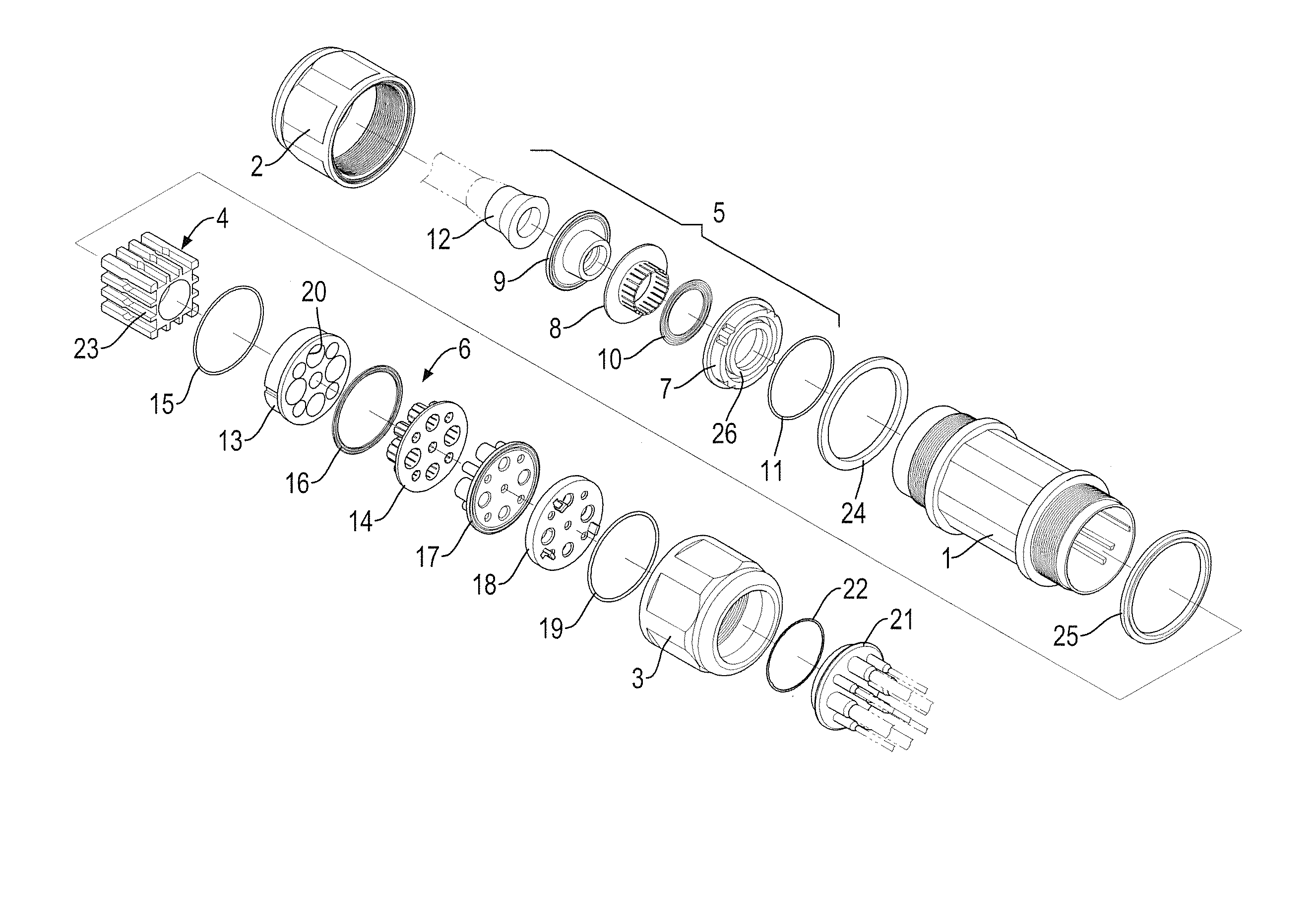
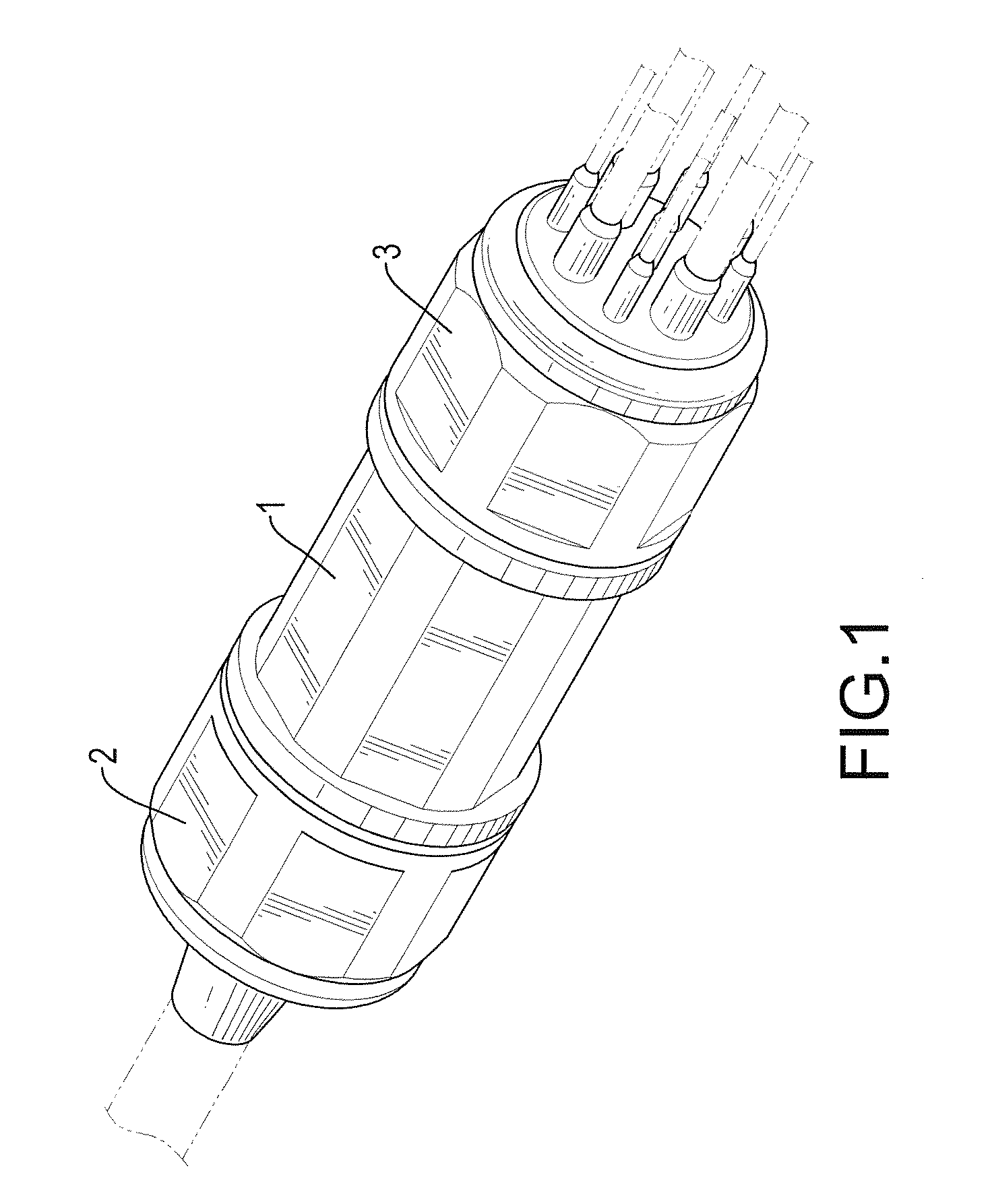
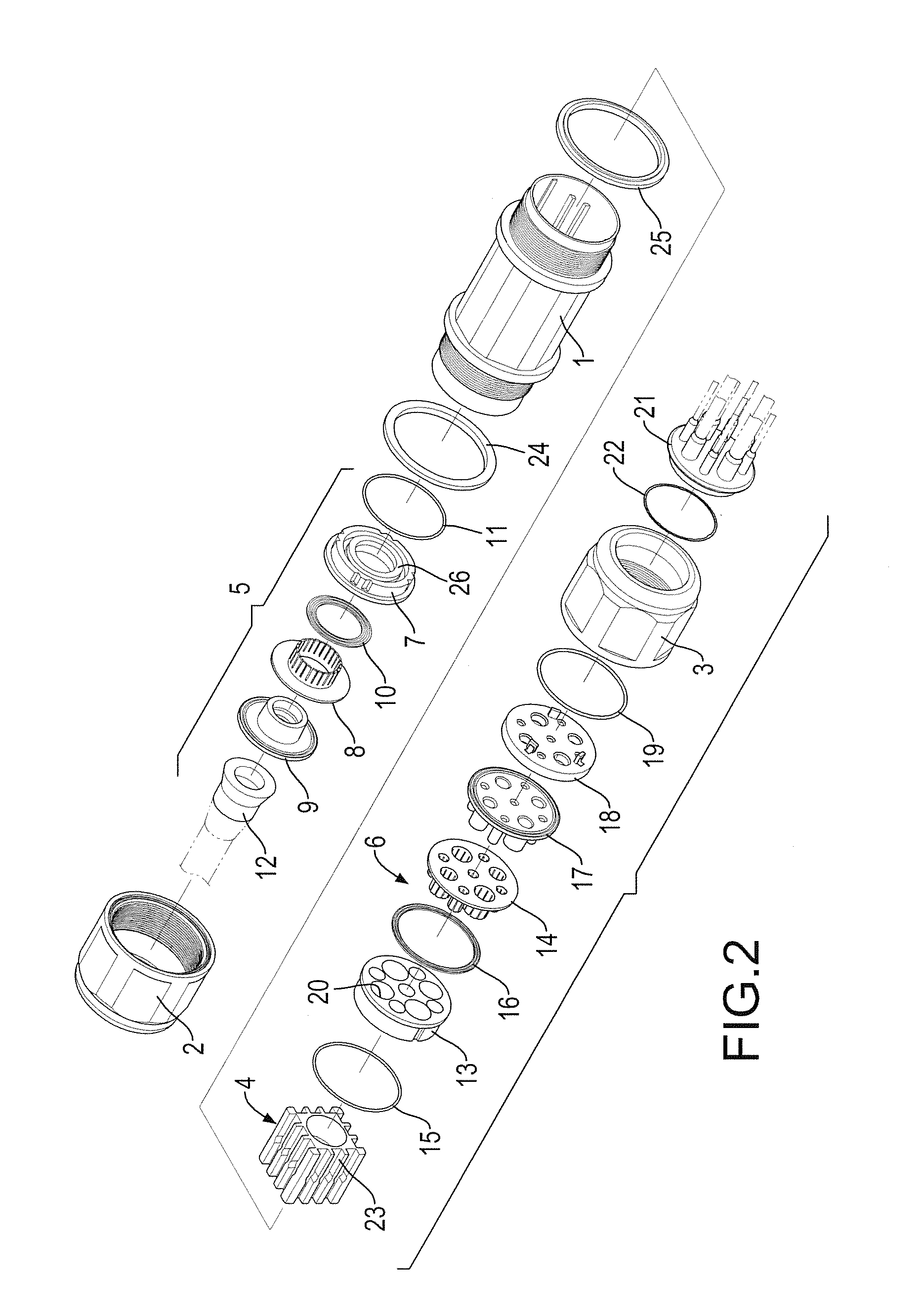
[0015]With reference to FIGS. 1 to 5, a cable connector in accordance with the present invention comprises a housing 1, an input cap 2, an output cap 3, a wire separating base 4, a cable sealing assembly 5 and a wire sealing assembly 6. The housing 1 is hollow and has an input end and an output end. The input cap 2 is mounted on the input end of the housing 1. The output cap 3 is mounted on the output end of the housing 1 so as to define a sealed space between the housing 1, the input cap 2 and the output cap 3. The wire separating base 4, the cable sealing assembly 5 and the wire sealing assembly 6 are mounted in the sealed space between the housing 1, the input cap 2 and the output cap 3. A first sealing ring 24 is mounted around the input end of the housing 1, and a second sealing ring 25 is mounted around the output end of the housing 1. Accordingly, an excellent sealing and water-proofing effect is provided between the housing 1 and the caps 2,3.

[0016]The wire separating base 4...


PUM


Abstract

A cable connector has a hollow housing, an input cap, an output cap, a wire separating base, a cable sealing assembly and a wire sealing assembly. The hollow housing has an input end and an output end. The input cap is mounted on the input end of the housing. The output cap is mounted on the output end of the housing so as to define a sealed space between the housing, the input cap and the output cap to hold the wire separating base, the cable sealing assembly and the wire sealing assembly inside. The wire separating base is mounted in the housing and has a first end and a second end. The cable sealing assembly is connected to the first end of the wire separating base. The wire sealing assembly is connected to the second end of the wire separating base.

Description

BACKGROUND OF THE INVENTION[0001]1. Field of the Invention[0002]The present invention relates to a cable connector, and more particularly to a water-proofing cable connector that can separate a cable into multiple branch wires.[0003]2. Description of Related Art[0004]A cable or optical fiber is used to transmit electrical power or communication signal. To connect the cable or the optical fiber to an electrical power machine or a communication machine, the cable or the optical fiber has to be separated into multiple wires, and the wires have to be positioned and sealed to keep water and moisture enters into the cable or the optical fiber.[0005]However, to position and seal the separated branch wires of the cable or the optical fiber is difficult and laborious. A conventional connector is applied to position the separated branch wires, but the sealing effect of the conventional connector is not sufficient. A water-proofing connector is also applied to provide a better water proofing e...

Claims


Application Information

Patent Timeline
IPC IPC(8): H02G3/18
CPCH02G15/013H02G15/117H02G15/115
Inventor LIN, CHENG-HSING
Owner ASIA TAI TECH
Why Eureka
Try Eureka