Utility powered communications gateway

a technology of utility communication and gateway, applied in the field of utility communications, can solve the problems of automatic defrosting of a refrigerator, inability to realize many of the benefits of smarter grid, and very little real-time information about the utility's distribution grid, and achieve the effect of high-power devices

Inactive Publication Date: 2013-08-20
GENERAL ELECTRIC CO
View PDF11 Cites 229 Cited by
  • Summary
  • Abstract
  • Description
  • Claims
  • Application Information

AI Technical Summary

Problems solved by technology

Without DMS, the utility gets very little real-time information about the distribution grid and can't realize many of the benefits of a smarter grid.
Or, the automatic defrost on a refrigerator can delay itself until a time of reduced electricity rates.
Under conditions of tight electricity supply, demand response can significantly decrease the peak price and, in general, electricity price volatility.
Because of the need to communicate with both networks, the meters are required to include devices configured for communications with each network, which can be expensive and redundant.
Furthermore, isolated power supplies are required in the meters to isolate the power used by these communication devices from metered power.

Method used


Image

  • Utility powered communications gateway
  • Utility powered communications gateway
  • Utility powered communications gateway

Examples


Embodiment Construction

[0028]Before the present methods and systems are disclosed and described, it is to be understood that the methods and systems are not limited to specific synthetic methods, specific components, or to particular compositions. It is also to be understood that the terminology used herein is for the purpose of describing particular embodiments only and is not intended to be limiting.

[0029]As used in the specification and the appended claims, the singular forms “a,”“an” and “the” include plural referents unless the context clearly dictates otherwise. Ranges may be expressed herein as from “about” one particular value, and / or to “about” another particular value. When such a range is expressed, another embodiment includes from the one particular value and / or to the other particular value. Similarly, when values are expressed as approximations, by use of the antecedent “about,” it will be understood that the particular value forms another embodiment. It will be further understood that the e...


PUM


Abstract

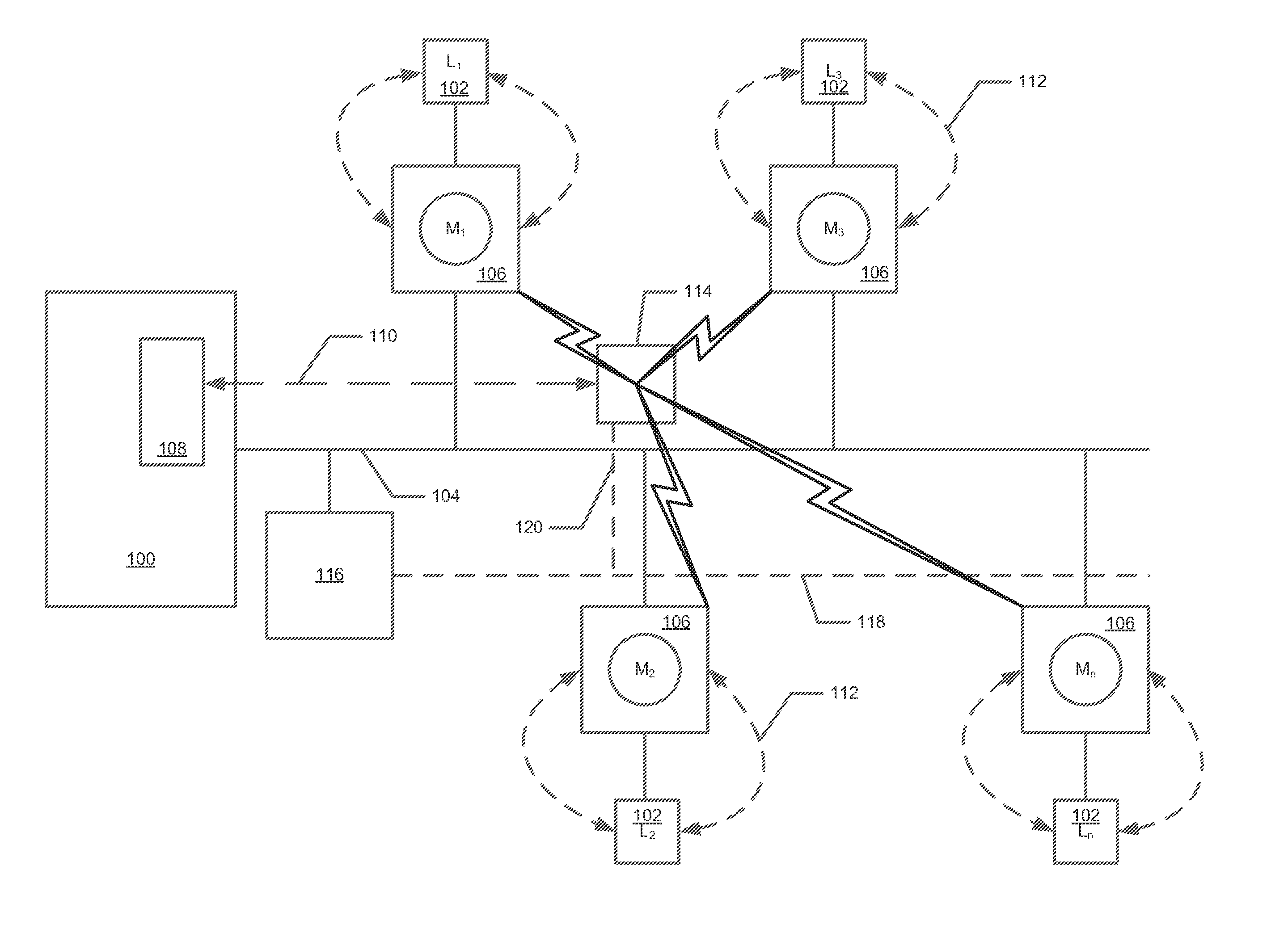
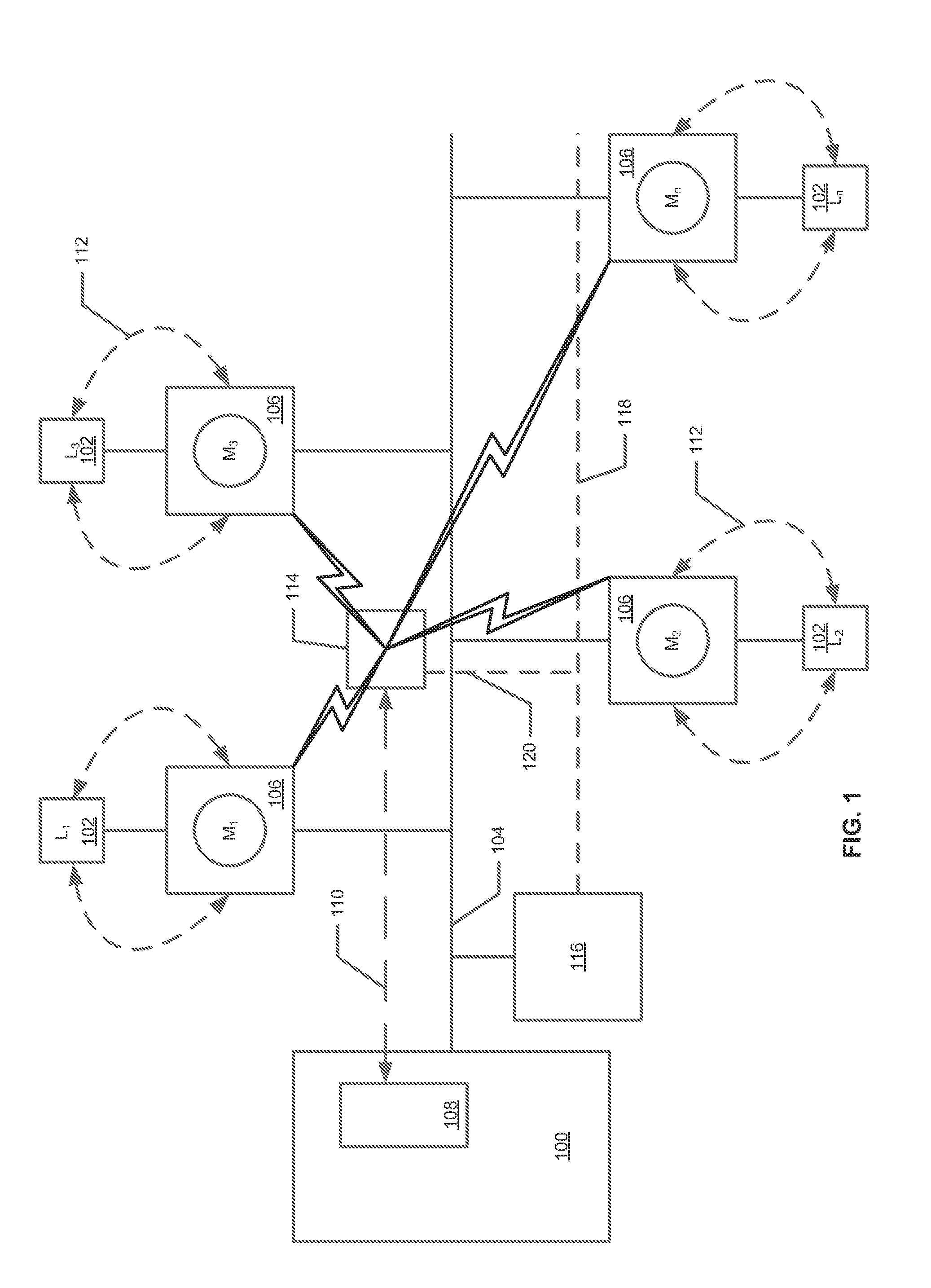
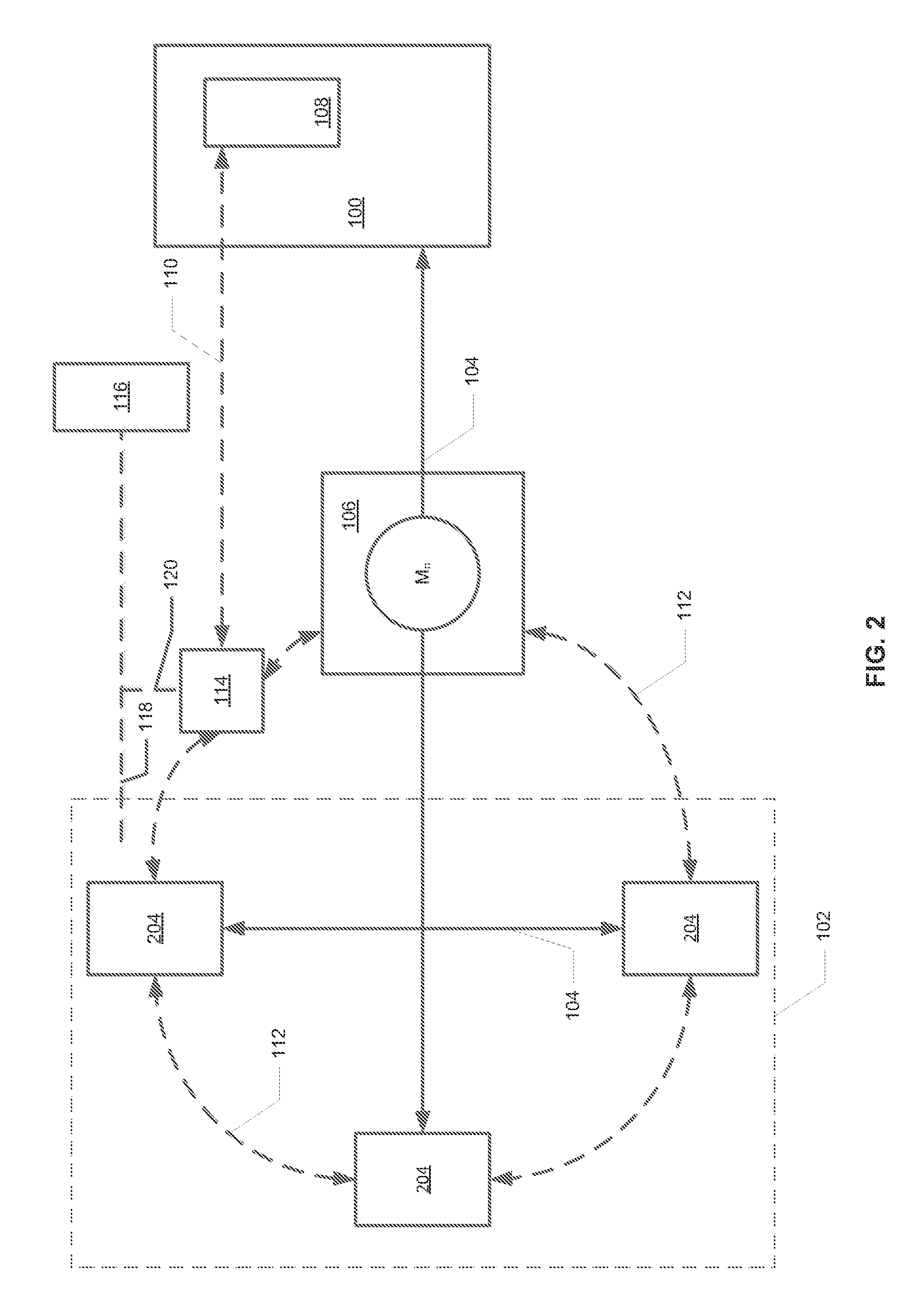
Described herein are embodiments of methods, systems and devices of providing a communications gateway between one or more first networks and a second network. In accordance with one aspect, a method is provided comprising receiving, by a first device, information communicated from one or more first networks, wherein the first device is a low power device; and transmitting, by a second device, at least part of the information over a second network, wherein the second device is a high power device and wherein the first device and the second device receive power from a wired communications system.

Description

FIELD OF THE INVENTION[0001]This invention generally relates to utility communications, and in particular, to systems, methods, and apparatus for providing a gateway for communications between one or more first networks and a second network.BACKGROUND OF THE INVENTION[0002]The increasing demand for energy and the use of finite resources for energy production have led to the use of increased technology for the production, transmission, distribution and consumption of energy in order to make, distribute and use energy more efficiently and wisely. To that end, utility service providers have begun employing information technology systems integrated with their energy production, transmission, distribution and metering systems to enable more efficient monitoring and operation of such systems. Concurrently, vendors and manufacturers have also begun employing similar technology in products and devices that consume electricity, such as appliances (e.g., refrigerators, washing machines and dr...

Claims


Application Information

Patent Timeline
Patent Type & Authority Patents(United States)
IPC IPC(8): H04M9/00
CPCH04L12/2803
Inventor PRINCE, CHRISTOPHER TERRYREE, BRADLEY RICHARD
Owner GENERAL ELECTRIC CO
Why Eureka
Try Eureka