Fluid regulator

a technology of flue gas regulator and regulator, which is applied in the direction of mixer, liquid dispensing, heating types, etc., can solve the problems of many liters of cold potable water that are not utilized by users and are lost to drain, and achieve the effect of overcoming or minimizing the problem of cold water loss

Inactive Publication Date: 2013-08-27
CULLIN PETER JAMES MR
View PDF11 Cites 26 Cited by
  • Summary
  • Abstract
  • Description
  • Claims
  • Application Information

AI Technical Summary

Benefits of technology

[0006]The present inventors have now invented a fluid regulator and method of fluid regulation which, inter alia, minimize or overcome the problem of cold water loss referred to above.
[0021]The collection chamber may have a vent for releasing air from the chamber when being filled with fluid and for introducing air into the chamber when fluid is being drained from the chamber. Any suitable type of vent may be used. In one embodiment, the vent extends from the chamber to the flow passage adjacent the outlet. In another embodiment, the vent has an outlet located in a peripheral wall of the body and has an inlet that may be positioned as required within the collection chamber, so as to control the level of fluid within the chamber.
[0036]In yet another embodiment, the flow diverter comprises a valve member that is movable relative to the body of the regulator, the valve member containing a section of the flow passage that is in fluid communication with the fluid collection chamber. In the closed position, the valve member is orientated relative to the regulator body such that the fluid stream is directed to the collection chamber and in the open position valve member is orientated relative to the regulator body such that the fluid stream may flow to the outlet. Preferably, the section of the flow passage contained by the valve member has the constriction / throat, so as to cause a Venturi effect.

Problems solved by technology

Consequently, many liters of cold potable water are not utilized by the user and are lost to drain.
Although water saving shower roses and shower heads are known, these address a different problem and do not address the problem of cold water loss.

Method used


Image

  • Fluid regulator
  • Fluid regulator
  • Fluid regulator

Examples


Embodiment Construction

[0065]In the figures, like reference numerals refer to like features.

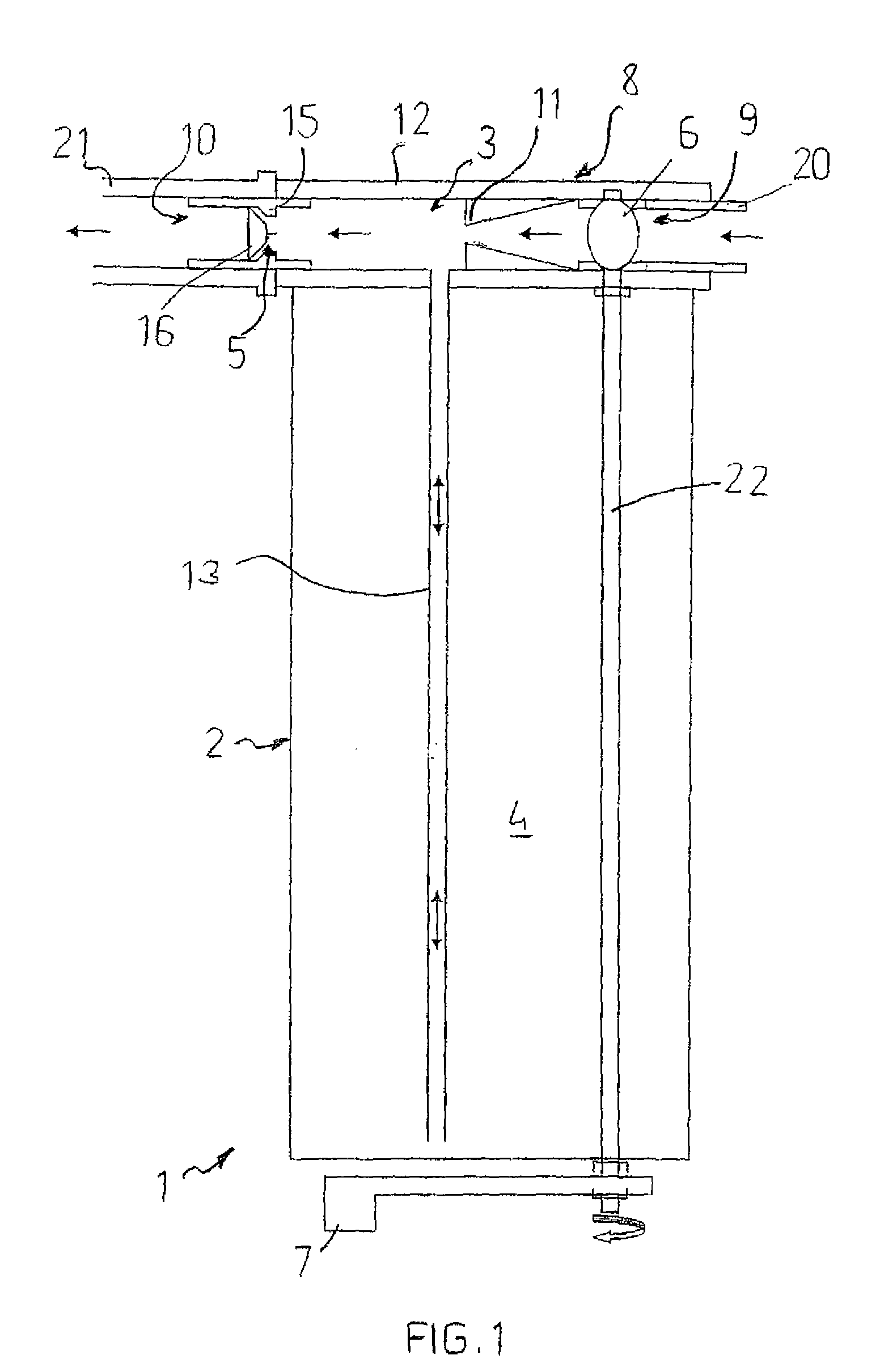
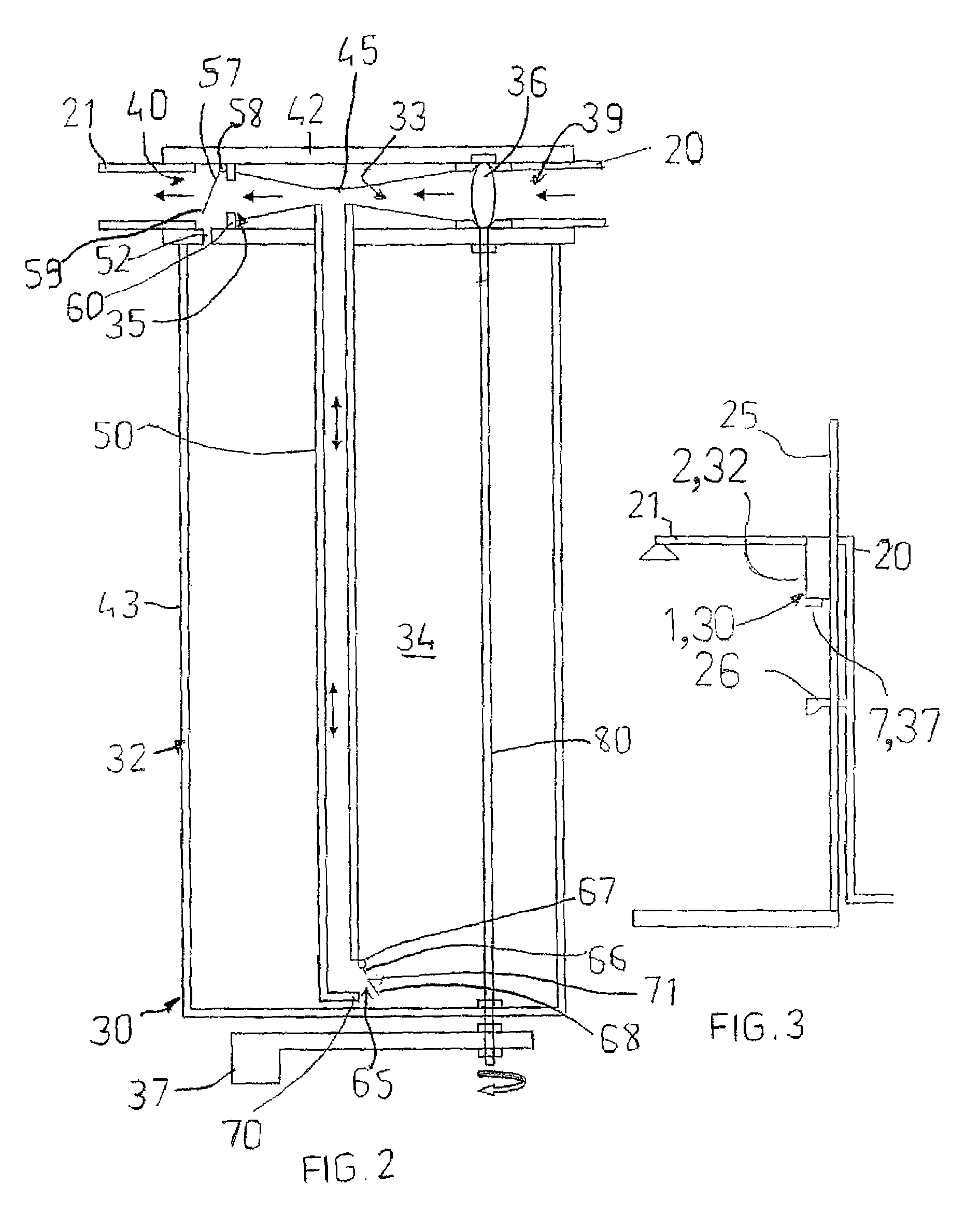
[0066]Referring first to FIG. 1, there is shown a fluid regulator 1 having a body 2, a flow passage 3, a fluid collection chamber 4, a flow diverter 5, and an inlet valve 6 operably connected to a lever 7.

[0067]The body 2 has an upper region 8 in the form of a lid that is detachable from a lower region of the body 2. The body 2 is cylindrical, as seen in FIG. 3. The body is made of injection moulded plastics material or metal.

[0068]The flow passage 3 extends lineally through the upper region 8 of the body 2. An inlet 9 is located at one end of the flow passage 3 and an outlet 10 is located at the other end of the flow passage. The flow passage 3 has a constriction / throat 11 intermediate the inlet 9 and outlet 10.

[0069]The chamber 4 is located within the lower region of the body 2 and is in fluid communication with the flow passage 3 by way of a conduit 13. The conduit 13 meets the flow passage 3 at a point downstre...


PUM


Abstract

A fluid regulator (1) for use as a shower water saving device, wherein an initial volume of water of a water stream at an undesired cold temperature is collected in a chamber and is reintroduced into the water stream when the stream has reached the desired temperature. Reintroduction of the initial volume of cold water is at a controlled rate such that the temperature change upon reintroduction is not significant. The fluid regulator (1) comprises a body (2), a flow passage (3) having an inlet (20) and outlet (21) for the water stream, a water collection chamber (4) in fluid communication with the flow passage (3), and a flow diverter (5) associated with the flow passage (3) and moveable between a closed position in which the water stream is directed to the collection chamber (4), and an open position in which the water stream may flow to the outlet (21) and the water in the collection chamber (4) may be drained from the collection chamber (4) to the outlet (21) by way of the flow passage (3).

Description

[0001]This application is a continuation in part of international application PCT / AU2007 / 000782 filed 4 Jun. 2007 which designated the US and additionally claims priority from Australian provisional patent application no. 2006903037 filed 5 Jun. 2006.FIELD OF THE INVENTION[0002]This invention broadly relates to a fluid regulator and to a method for regulating a fluid stream.[0003]The invention has been developed primarily for use as a shower water saving device and will therefore be described in this context. It is to be appreciated, however, that the invention may have other uses.BACKGROUND OF THE INVENTION[0004]The need to conserve potable water is becoming more important than ever before. Many water saving initiatives have been implemented by authorities, and many different types of water saving and water efficient devices and appliances are available in the marketplace.[0005]Approximately 10 million showers are taken daily in Australia. When a user of a shower initially turns on...

Claims


Application Information

Patent Timeline
Patent Type & Authority Patents(United States)
IPC IPC(8): B01F5/04
CPCE03B1/04E03B1/048E03C1/02F24D17/00Y10T137/0329Y10T137/6497Y10T137/85954Y10T137/86381Y10T137/87587Y10T137/87619Y10T137/87635Y10T137/87676
Inventor CULLIN, PETER
Owner CULLIN PETER JAMES MR
Why Eureka
Try Eureka